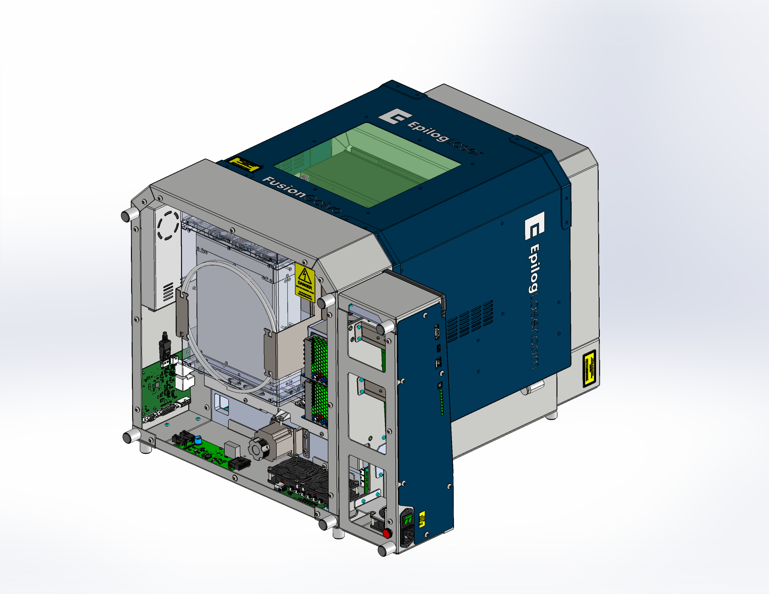
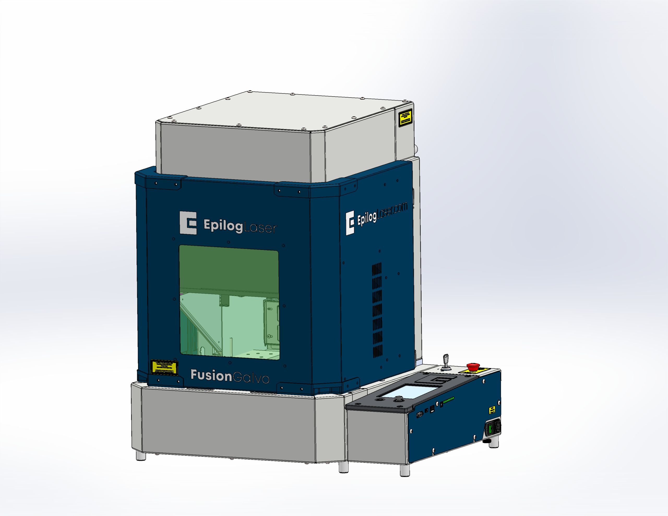
Replacing the rotary circuit board on the Fusion Galvo G100 laser is a critical maintenance procedure designed to restore or maintain optimal rotary function. This guide provides step-by-step instructions for safely accessing, removing, and installing the rotary circuit board. Proper handling and installation are essential to ensure continued precision and performance of the Galvo system. Before beginning, be sure to follow all recommended safety precautions and disconnect the laser from power.
Removing the Rotary Circuit Board (CS0852)
-
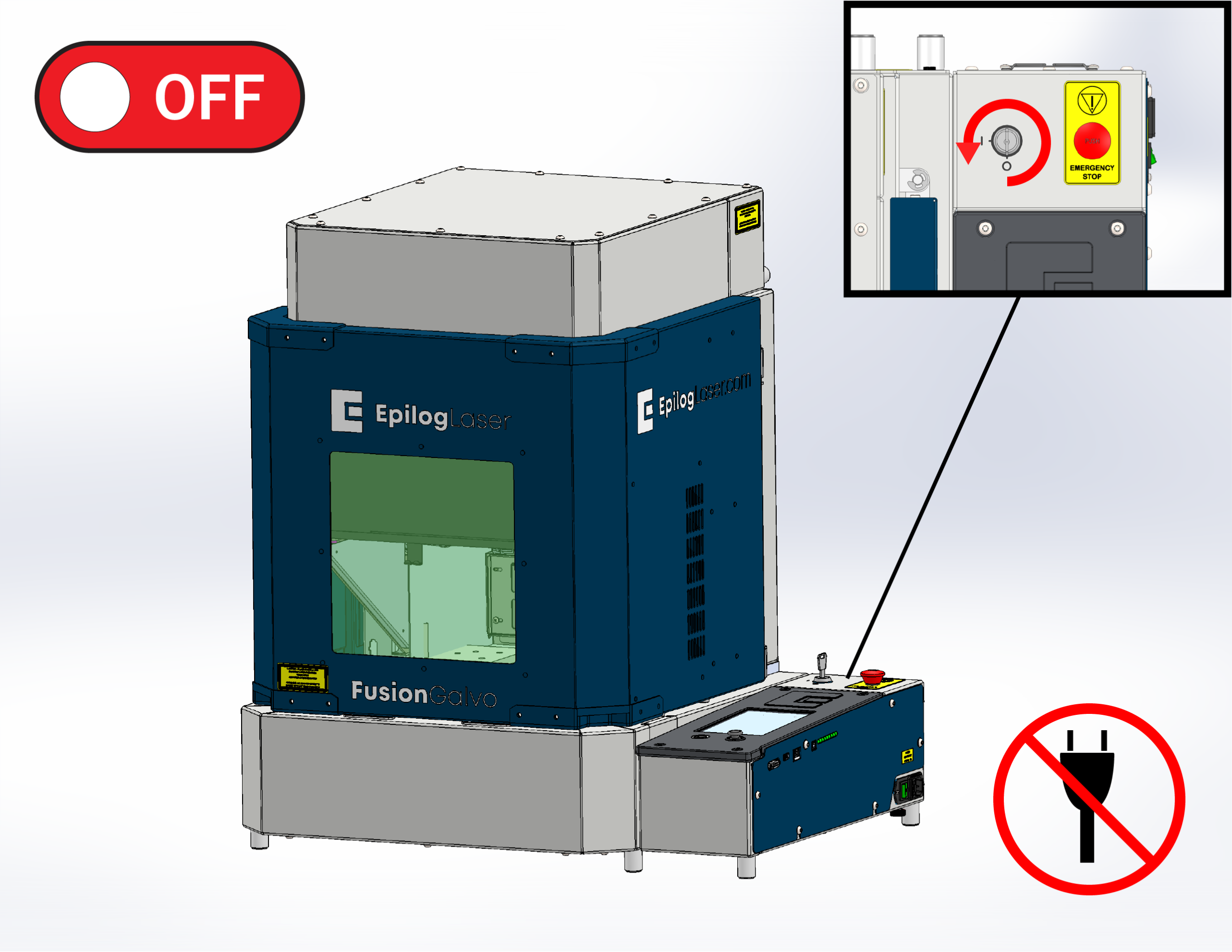
Power OFF and unplug the machine.
-
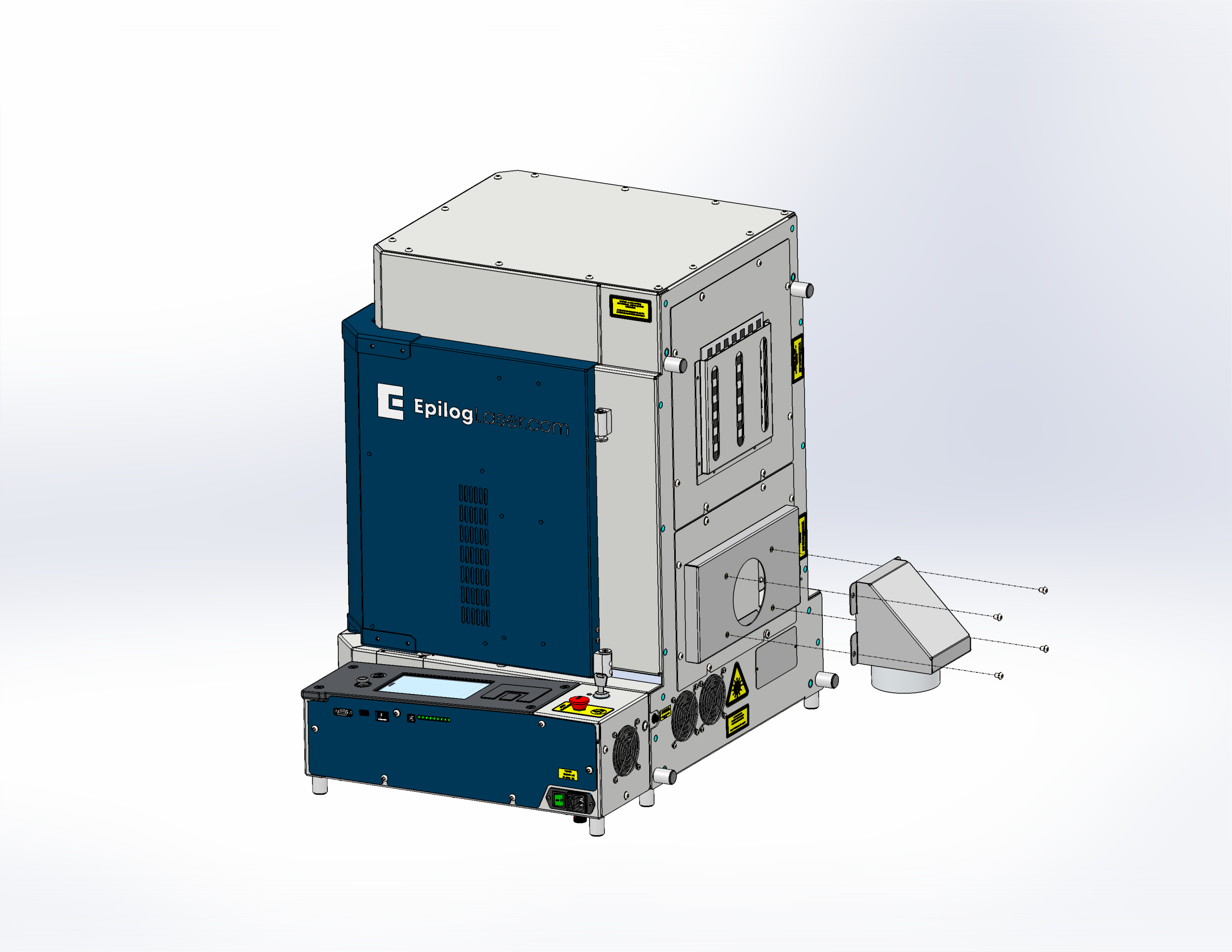
Remove rear exhaust port.
-
Carefully place the machine on its back.
Note: Remove any material or accessories inside the machine before proceeding with this step.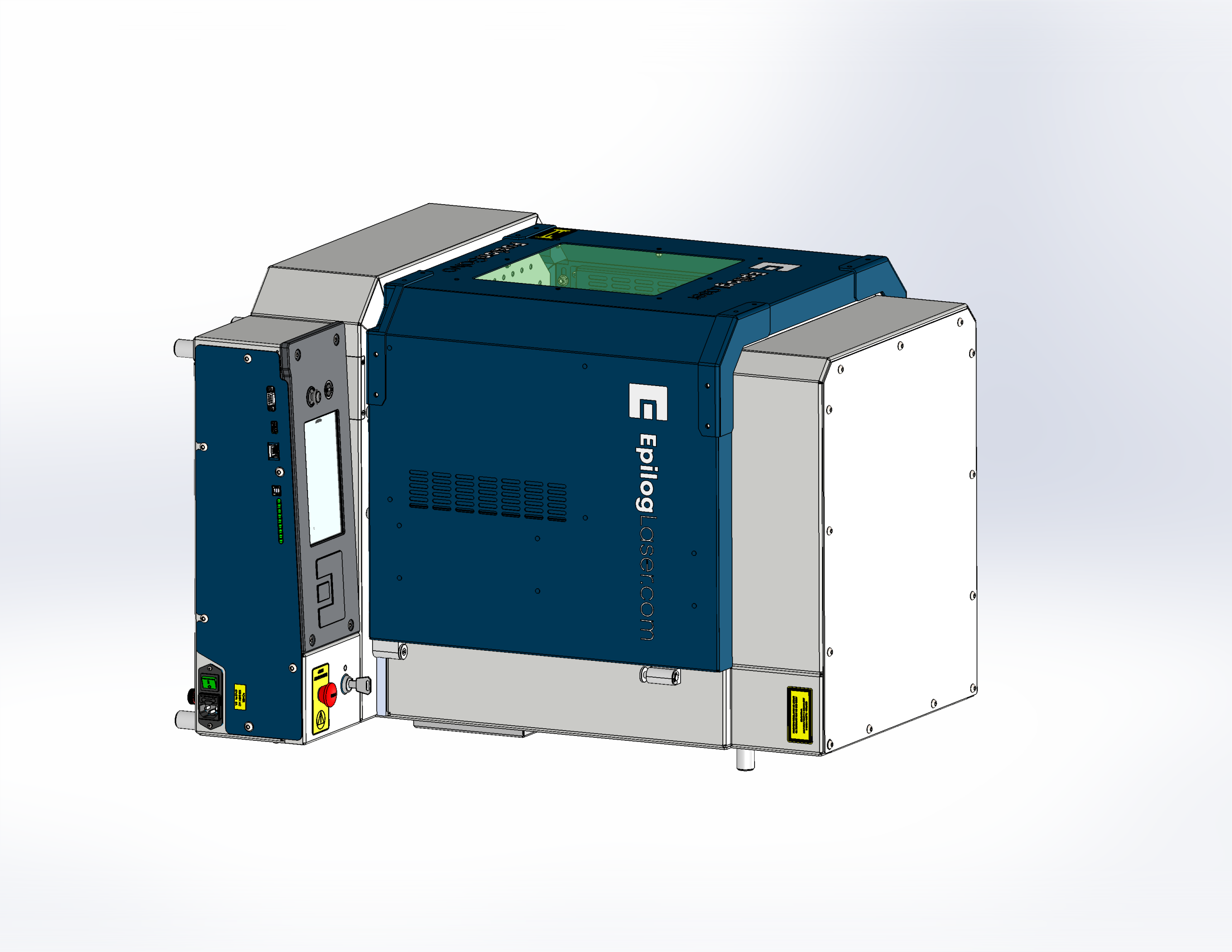
-
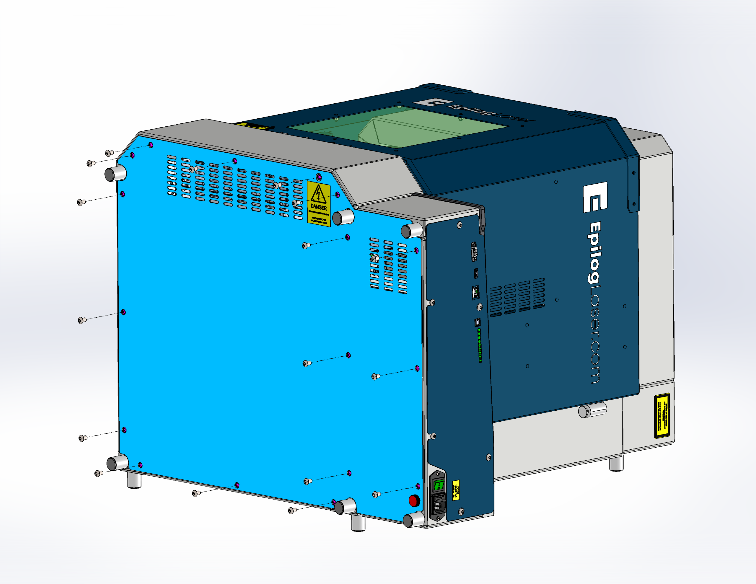
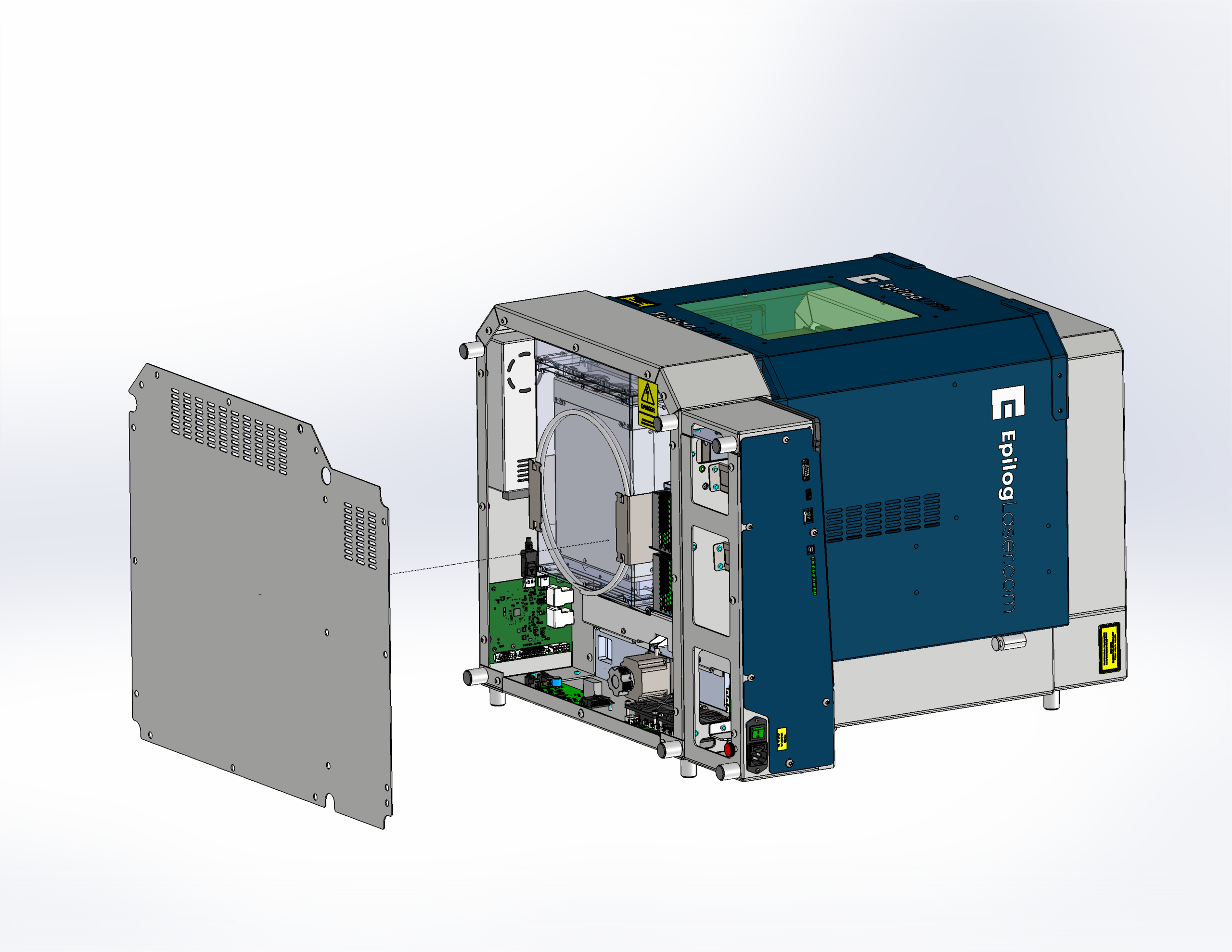
Remove bottom panel.
-
Attach the antistatic wrist strap securely to a bare metal part of the machine, then fasten the strap around your wrist.
Note: Always wear an antistatic wrist strap when handling electronic components to prevent electrostatic discharge (ESD) that can damage sensitive circuitry.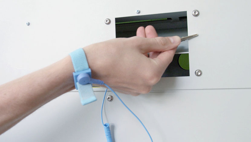
-
Disconnect the electrical connections from the rotary circuit board.
Note: Hover over the icon to view an animation of the step. -
Remove screws and lift out the rotary circuit board.
Note: Hover over the icon to view an animation of this step.
Installing the Rotary Circuit Board (CS0852)
-
Secure the rotary circuit board in place and reinstall the mounting screws.
Note: Hover over the icon to view an animation of this step. -
Reconnect the electrical harnessing to the rotary circuit board.
Note: Hover over the icon below to view an animated demonstration of this procedure. -
Detach the antistatic wrist strap from the machine and remove it from your wrist.

-
Reinstall the bottom panel.
-
Carefully return the machine to its upright position.
-
Reinstall the rear exhaust port.
-
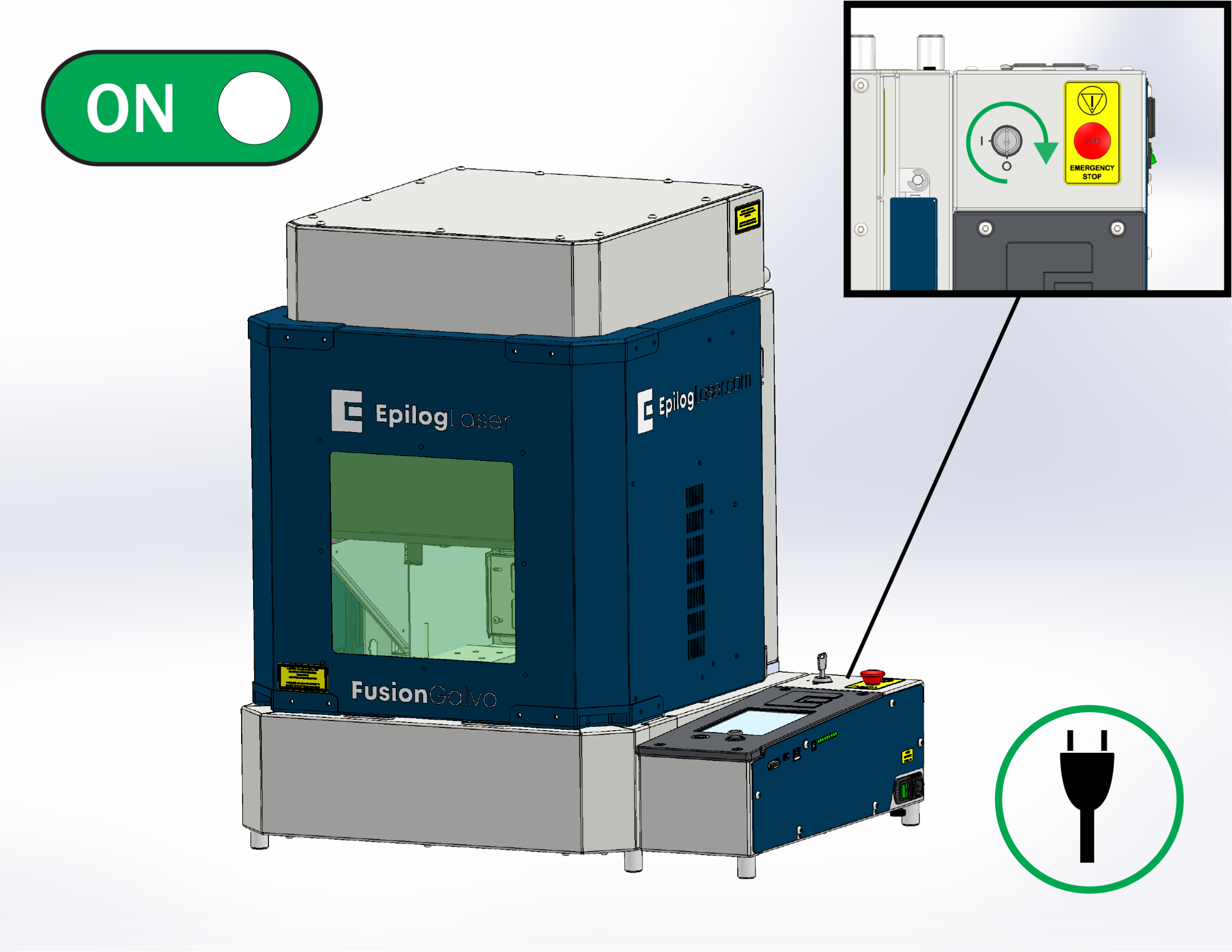
Plug in the machine and power ON to verify proper rotary function.