
This document will describe how the diagnostic LEDs function, and their behavior during the boot up sequence.
Locating the Diagnostic LEDs
The diagnostic LEDs are on the Control Assembly panel in the back of the
engraver. This panel also contains connections for Ethernet, USB and Air Assist. The
LEDs are labeled “Interlocks”, “Laser”, “Laser Control”, “CPU1, “CPU2” and “CAN Bus”.
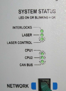
Interpreting the Diagnostic LEDs
- Interlocks
- Laser
- Laser Control
- CPU1
- CPU2
- CAN Bus
When the Interlocks LED is illuminated it indicates that the doors on the engraver
are closed. If the LED is not illuminated for any reason the laser will not fire, and in
some regions the engraver will cease mechanical movement.
This is a laser status LED. It will indicate whether the laser is working as
determined by the system. This led is controlled by CPU2.
This LED indicates whether or not the Control Assembly is sending control and
fire data to the laser tube. This LED will not be illuminated if the laser is not attempting
to fire. And will either flicker quickly or come on solid when the laser is attempting to fire.
If this LED comes on and the laser dose not fire then the Laser tube may not be
receiving the fire data, may be damaged, or the laser beam may not be getting to the
bed.
This LED will blink twice every second on boot to indicate that the Altera FPGA
and the iMX35 primary CPU are working. This LED will only indicate an error on boot.
This LED will blink once every second on boot. This indicates that the PIC32
auxiliary processer is functioning at the time of boot. This LED will only indicate an error
on boot.
This LED indicates that internal data network (Controller Area Network data
buses) is working. This is also an indirect indication that both of the CPUs are working
after boot. This LED will reflect valid data any time.

