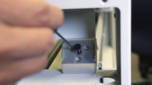
Proper laser alignment is critical to the cutting performance and engraving quality of your Epilog Fusion FiberMark. This diagnostic guide outlines the complete step-by-step alignment procedure required to safely restore optimal beam delivery. Whether you are correcting a general loss of power, addressing beam fading in specific table zones, or recalibrating the system after replacing core components like the laser tube or X-Axis rail, following these procedures will ensure your mirrors are perfectly dialed in for peak accuracy.
SAFETY WARNING
DO NOT PROCEED UNLESS YOU HAVE READ, AND UNDERSTAND THE FOLLOWING SAFETY WARNINGS.
This procedure requires that the laser be operated with the engraver’s door safety interlocks defeated or with protective covers removed. Do not fire the laser while the safety interlocks are defeated or when the side covers are removed. Safety glasses are required to be worn throughout the entirety of the following procedures.
When to align the laser:
The Laser Alignment Procedure can be performed if any of the following apply to you:
- You are experiencing a general Loss of Power.
- You are experiencing ‘Fading’ in one of the corners of the table.
- You are losing power in certain positions on the table.
- You have replaced the X-Axis Rail.
- You have replaced a Laser Tube.
- You have replaced a Mirror or Optic.
- The engraver has been moved or transported.
Overview & Before you start…
Direction
Many of the instructions provided in this procedure will have a direction given, such as left hand side or right hand side. Unless otherwise stated, these are all provided as though you were facing the machine from the front.
Table Positions
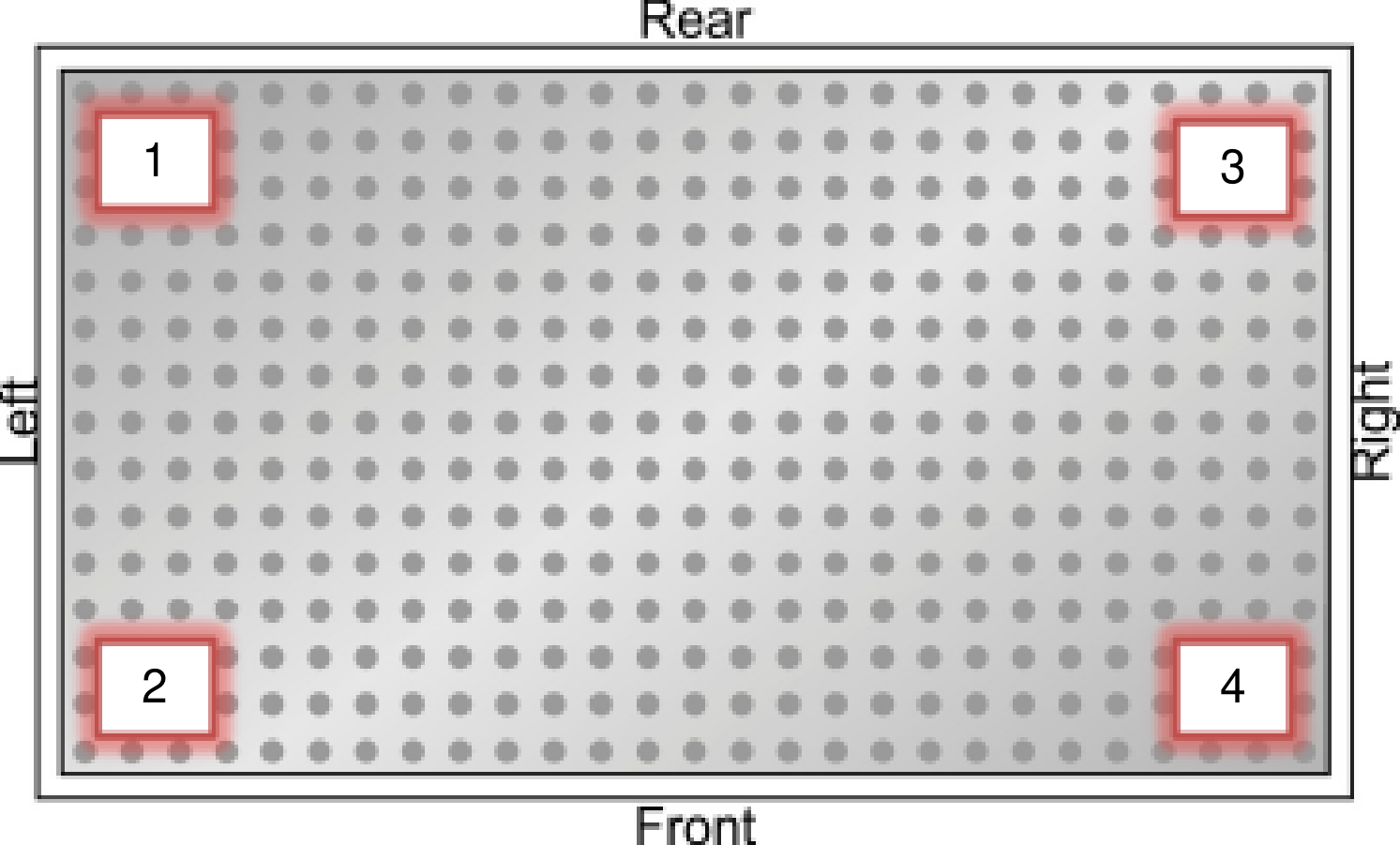
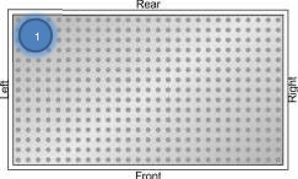
For the following procedures the table will be broken into four (4) positions. Each position is identified by its relative distance to the laser source and corresponds with the mirror to adjust for that position.
Mirrors
The three (3) adjustment mirrors used for alignment are on the left side of the engraver. The mirror numbers correspond directly with the positions on in the bed; for example, if the lens carriage is in Position #1 than you will only adjust Mirror #1.

Jogging the lens carriage
When moving the lens carriage on the engraver you will be use the “Jog” mode on the keyboard. When asked to move the lens carriage into a position you only need to move it as far as practical. Move the carriage as far into the requested corner as you can while maintaining the ability to see the red dot pointer on the alignment target.
Procedure A: Aligning the laser
Step 1: Remove the left hand panels
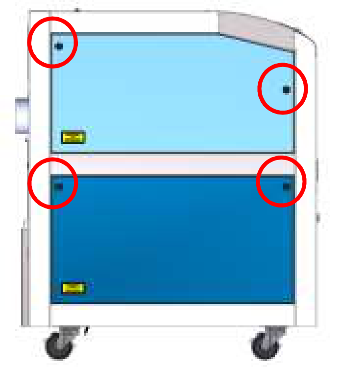
With the engraver powered on. Remove both the Left side Access Panels to gain access to the mirrors. There are two black Panel Locks per panel holding them in place. Using a 5/32″ Allen wrench, turn the black Panel Locks 1/4 of a turn counterclockwise. Place the panels aside.
Step 2: Remove upper mirror access panel
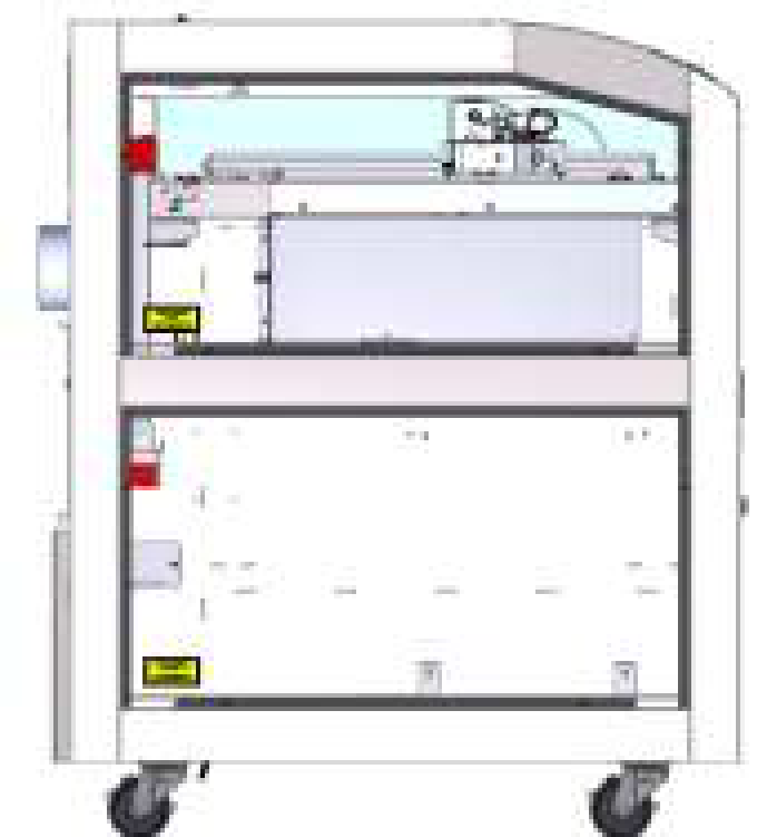
Using the #1 Screwdriver, remove the Upper Mirror Access Panel.
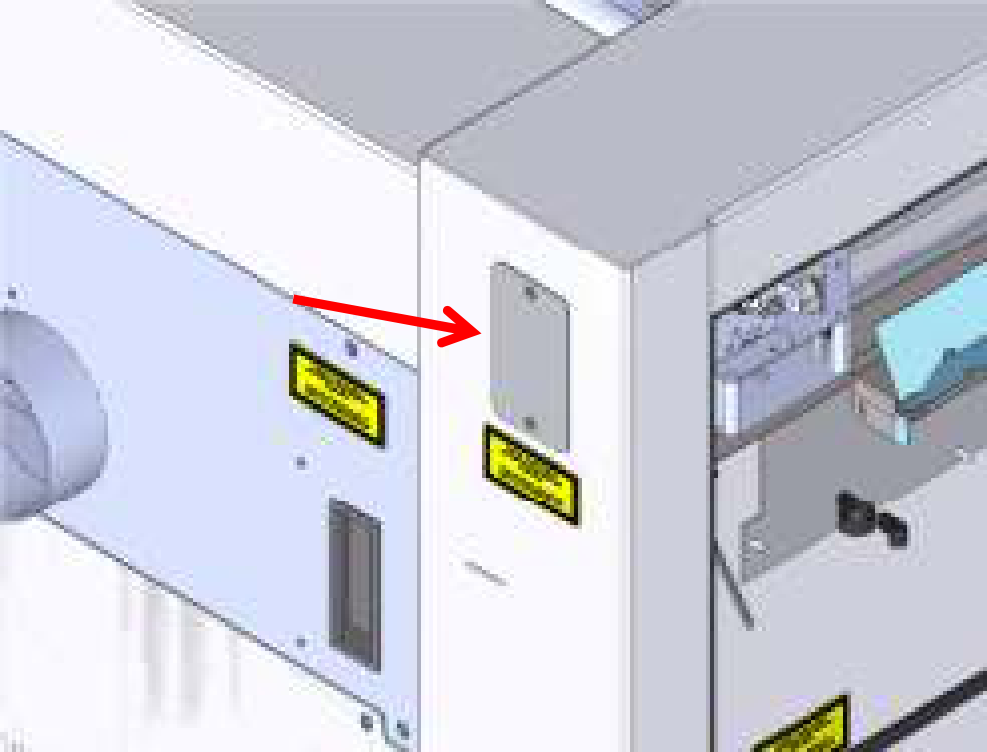
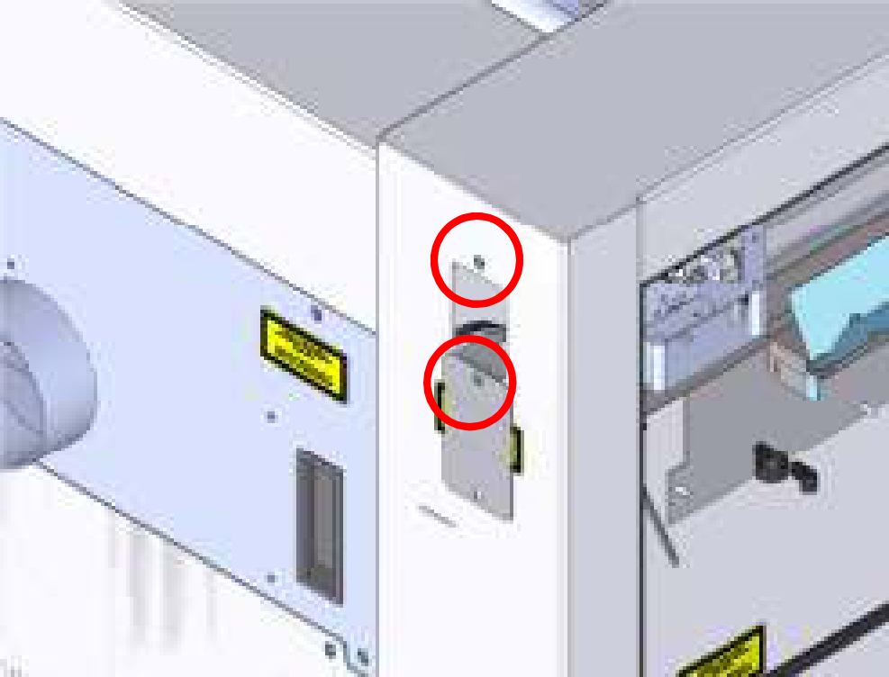
Step 3: Align mirror 1
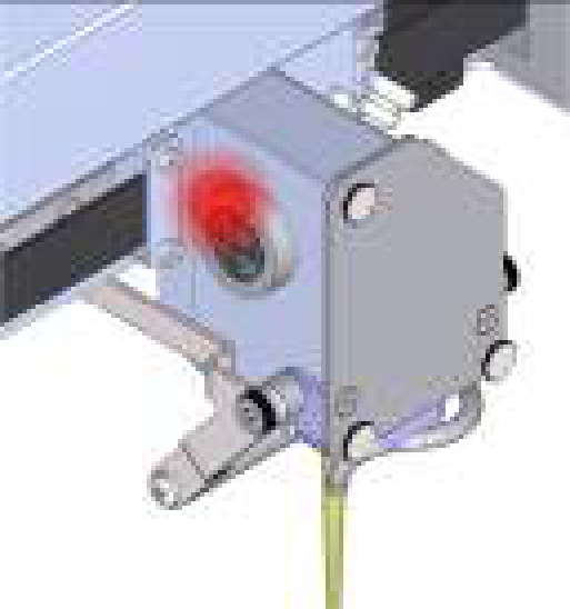
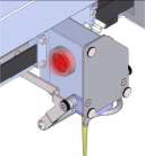
Ensure that the engraver is on and that the Red Dot Pointer is active [See A-7]. Jog the lens carriage to Position 1.
Quick Tip! The key to a good alignment is repetition and patience. For the best results take your time to dial it in.
Step 4: Align mirror 1
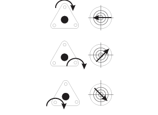
Locate Mirror #1. Using the 3/32″ Allan Wrench, adjust the screws on Mirror #1 so that the Red Dot Pointer is in the center of the alignment target.
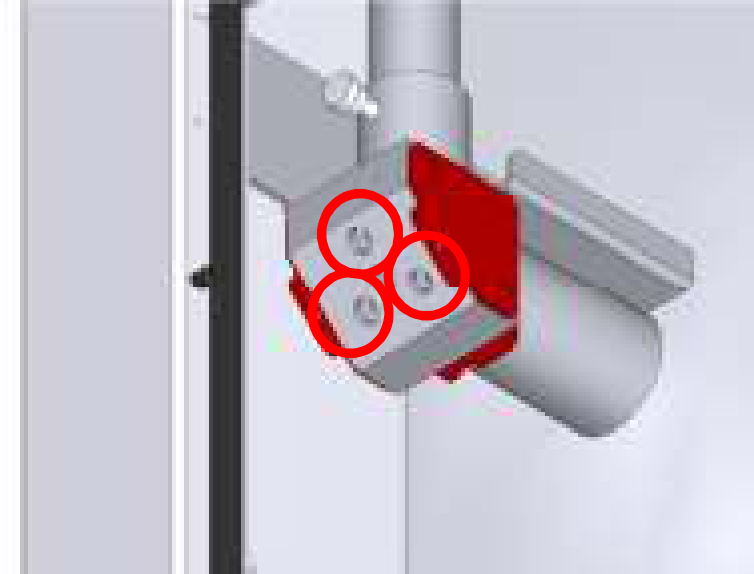
Step 5: Align mirror 2
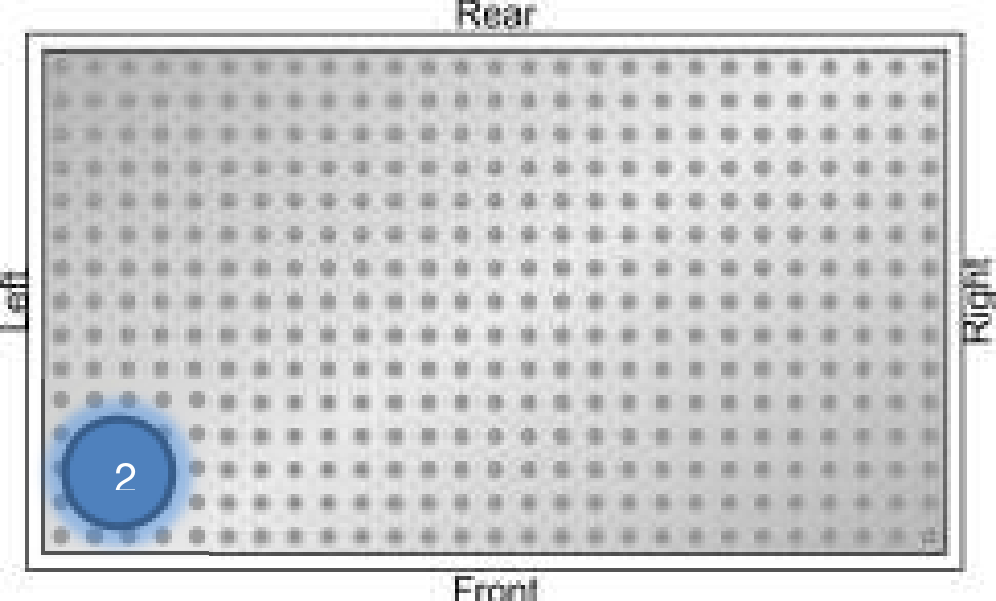
Jog the lens carriage to Position 2.
Step 6: Align mirror 2
Locate Mirror #2. Using the 3/32″ Allan Wrench, adjust the screws on Mirror #2 so that the Red Dot Pointer is in the center of the alignment target.
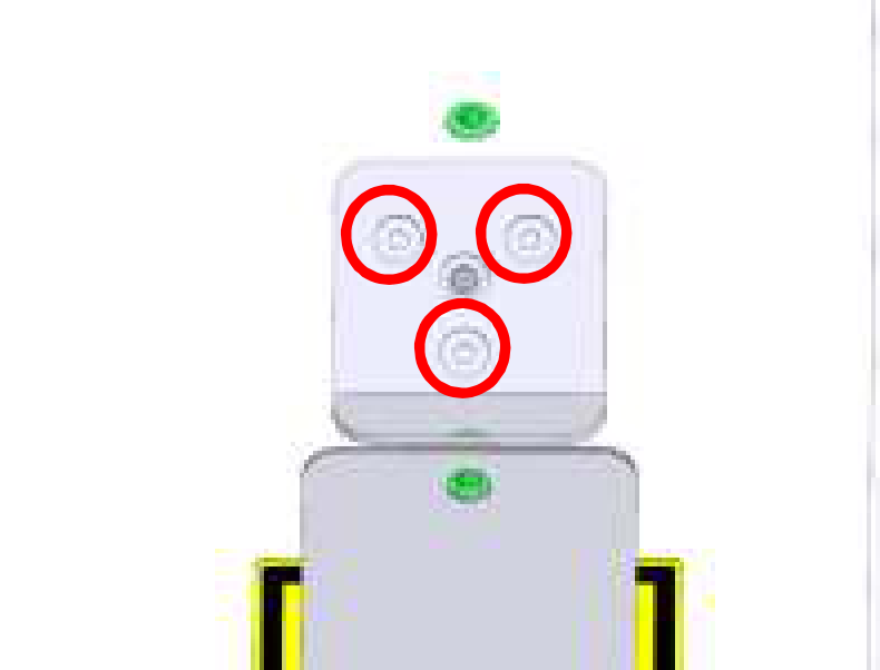
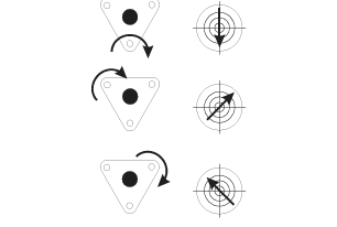
Once complete return to [Step 3]. Continue to align Mirror #1 and #2 until you can jog between them without the Red Dot leaving the Center of the alignment target.
Step 7: Align mirror 3
Jog the lens carriage to Position 3.
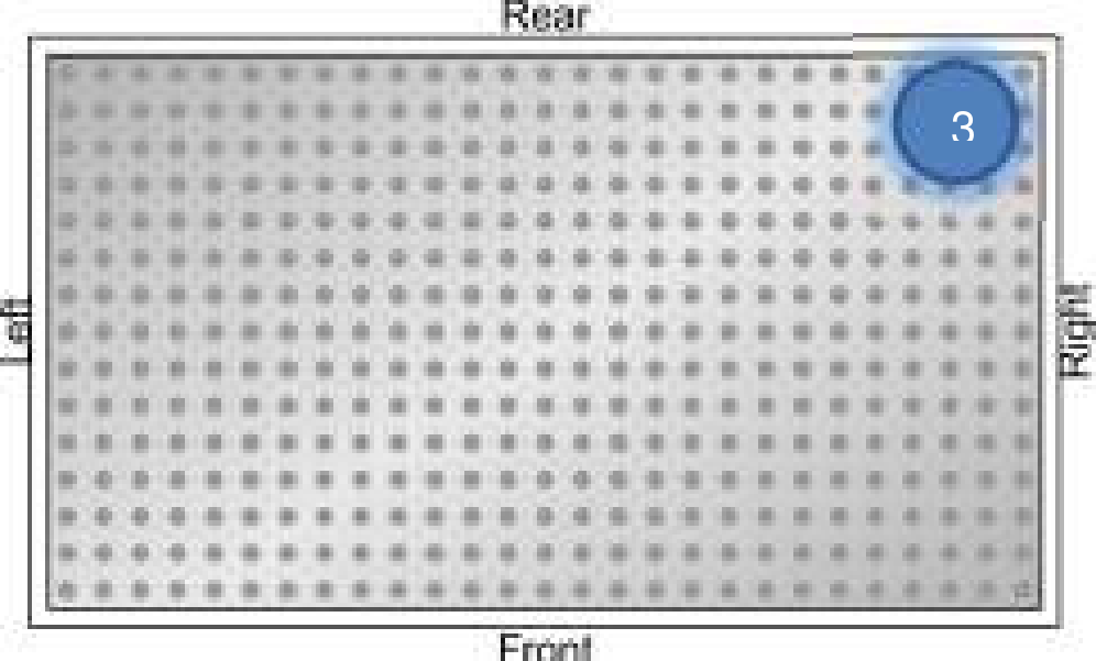
Step 8: Align mirror 3
Locate Mirror #3. Using the 3/32″ Allan Wrench, adjust the screws on Mirror #3 so that the Red Dot Pointer is in the center of the alignment target.
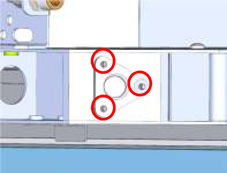
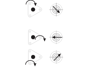
Once complete return to [Step 3] and then [Step 5]. Continue to align Mirrors #1, #2 and #3 until you can jog between them without the Red Dot leaving the Center of the Alignment Target.
Step 9: Check
Once you are confident that you can between Positions #1, #2 and #3, jog the lens carriage to Position #4.
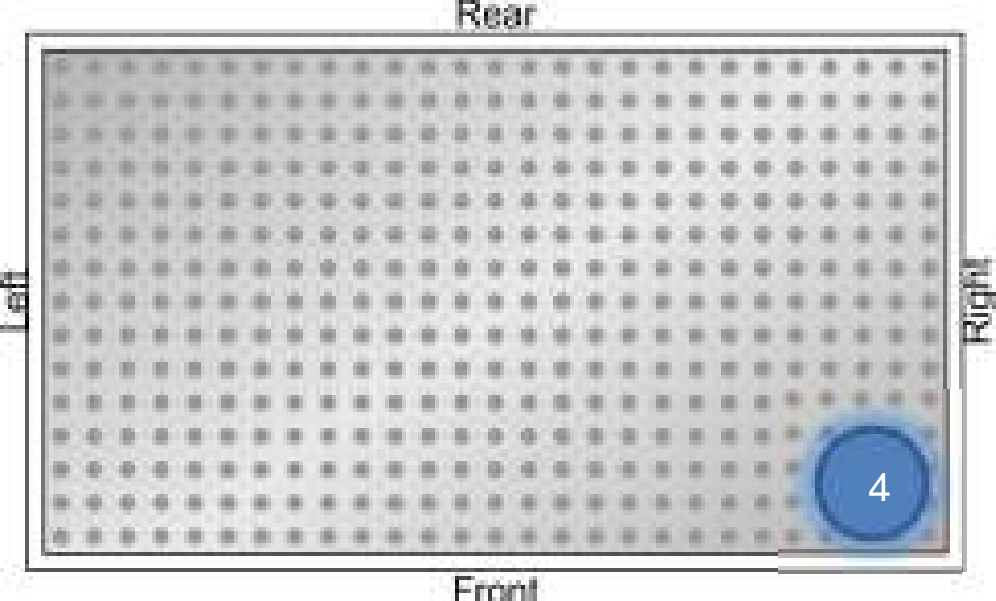
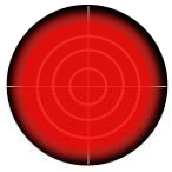
If all of the mirrors are aligned correctly, the red dot pointer should appear to cover the target. If so; you may remove the alignment target, replace the panels and run a test engraving file. If not; please return to [Step 3] and continue alignment.
Procedure B: Perpendicular Alignment
Step 1:
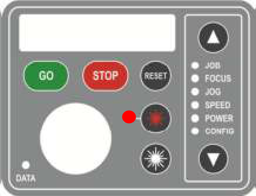
Ensure that the engraver is on and that the Red Dot Pointer is active [See A-7]. Use the Arrow Keys on the engraver’s keypad to navigate to Focus mode and double click the joystick.
Step 2:
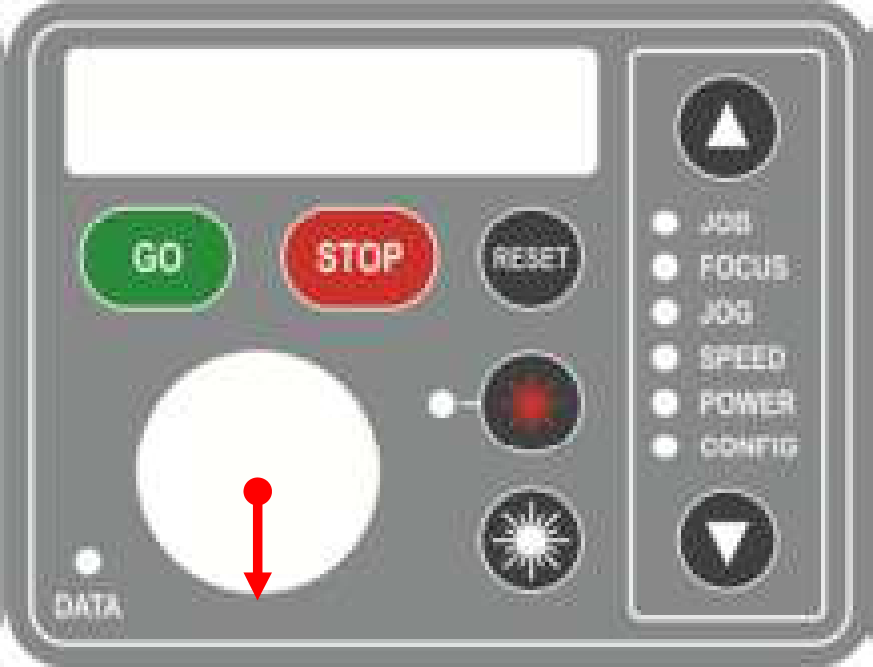
Push Down on the joystick to bring the engraver head onto the table. The joystick is represented by the large circle in the lower left side of the display.
Step 3:
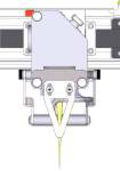
Place the manual focus gauge on the lens carriage, and use the joystick to focus the engraver to the table. Click the joystick to set the focus to 0.000.
Step 4:
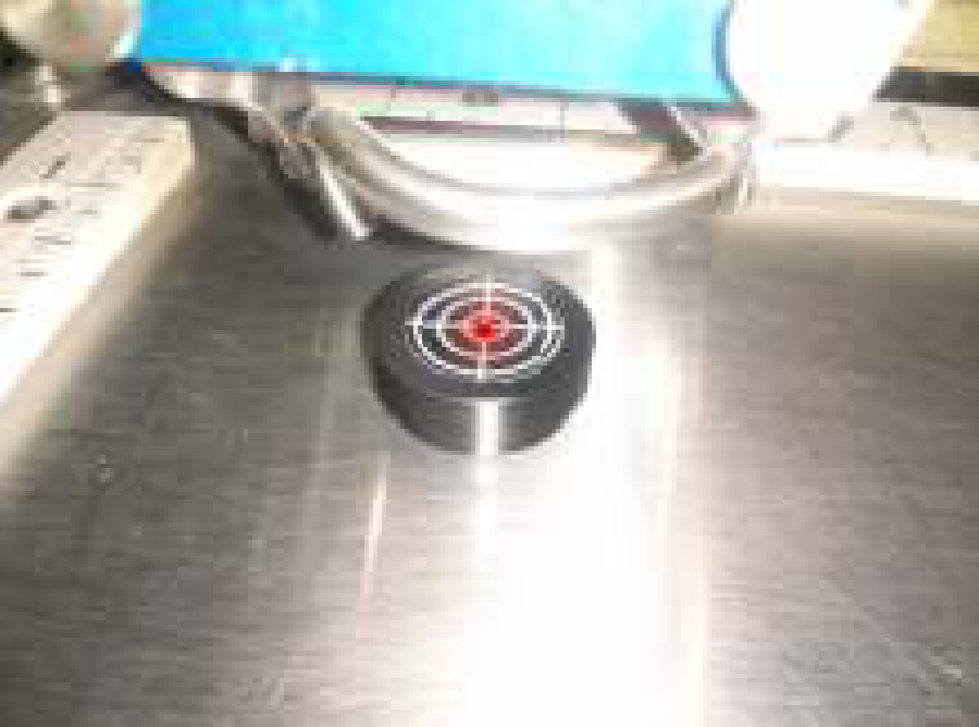
Position the alignment target on the table so that the Red Dot Pointer is in the center of the target.
Step 5:
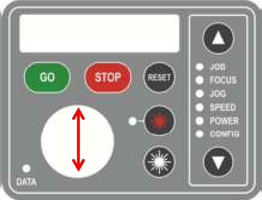
Using the joystick on the keypad, lower the bed of the table until the display reads around +3.000.
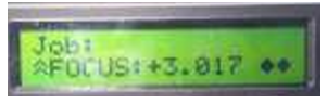
Step 6:
Check the location of the Red Dot Pointer and see if it has moved off of the center of the alignment target.
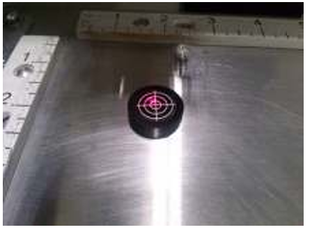
Step 7:
Use the adjustment screws on the Carriage Mirror to move the Red Dot Pointer back onto the center of the target.
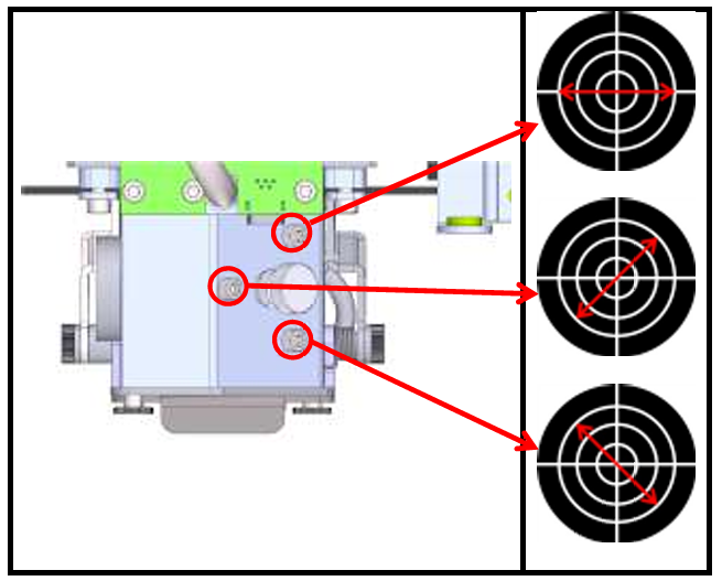
Step 8:
Using the joystick on the engraver’s keypad, bring the bed back up until the display reads around 0.000.
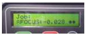
Step 9:
Repeat [Step 4] through [Step 8] until you can rise and lower the table without the Red Dot moving on the Alignment Target.