This guide covers replacing the backplane board on the Fusion Pro 32 and 48. After installation, the new board is programmed from the engraver’s display.
Parts Required
- CS0348 – PCBA, Backplane
Tools / Materials Required
- T8 Torx Driver
- Phillips Screwdriver
- Anti-Static Strap
Safety First: Ensure the engraver is completely powered off and the power cord is disconnected before removing any panels or touching internal electronics.
Static Warning: The backplane board is sensitive to static discharge. Wear a grounded anti-static strap while handling it.
Backplane Board Removal
Turn Off Engraver
Turn off the engraver.
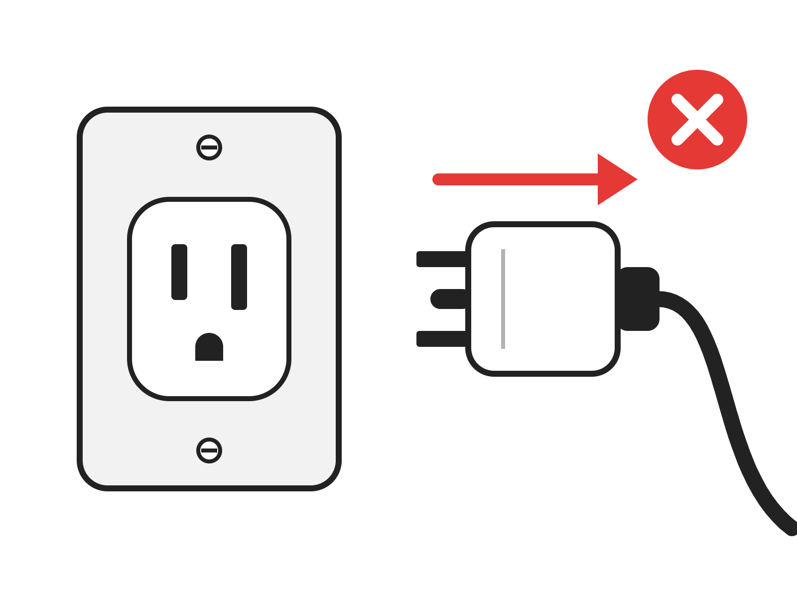
Disconnect from Power
Unplug the engraver from its power source.
Disconnect Cables
Disconnect any connection cables from the engraver, such as USB, Ethernet and fan control.
Put On Anti-Static Strap
Place the anti-static strap around your wrist and attach the clamp to a bare metal surface on the engraver.
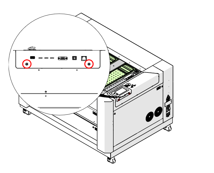
Loosen Control Module Screws
Loosen the two Phillips screws on the control module (circled in red).
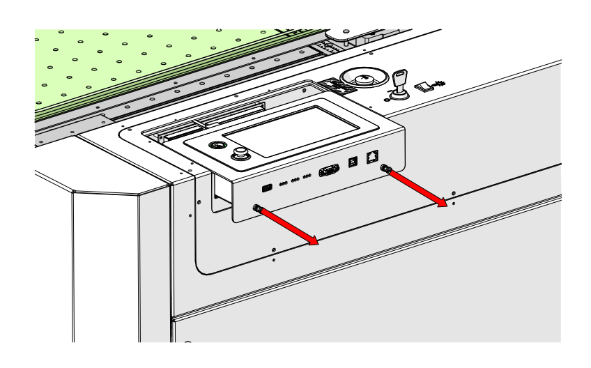
Pull Out Control Module
Grip the two Phillips screws and gently pull the control module straight away from the engraver.
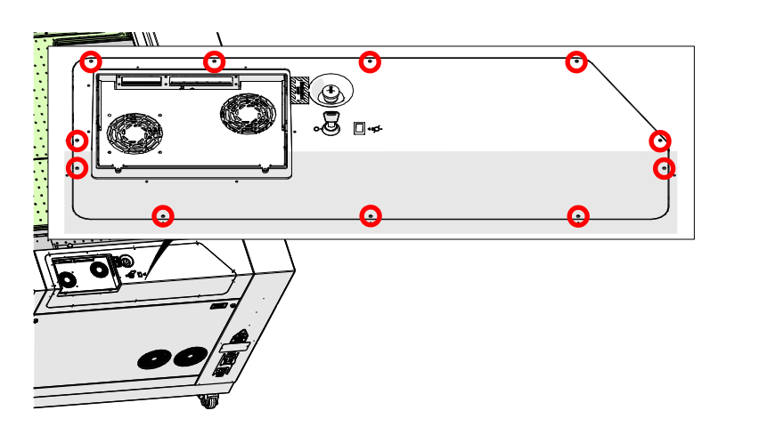
Remove Corner Panel Screws
Loosen and remove the nine T8 Torx screws on the upper right corner panel (circled in red).
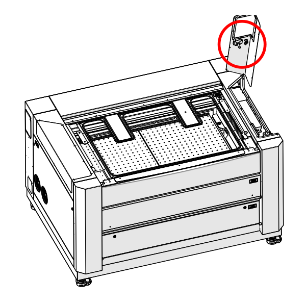
Lift Corner Panel
Gently lift the upper right corner panel and disconnect the key switch and emergency stop connections (circled in red).
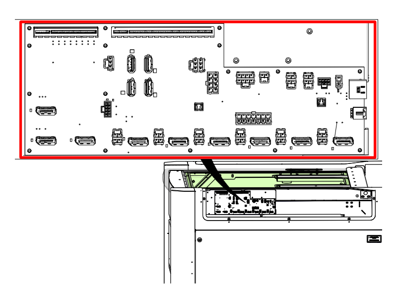
Disconnect Harnesses
Disconnect the electrical harnesses from the backplane board.
Note: Each receptacle and its harness are labeled. Taking a photo of the connections before you remove them makes reconnecting easier.
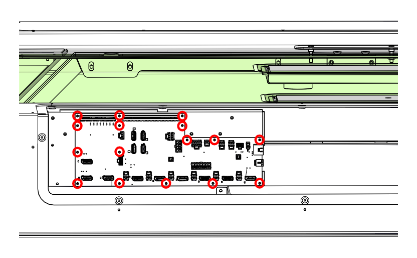
Remove Board Screws
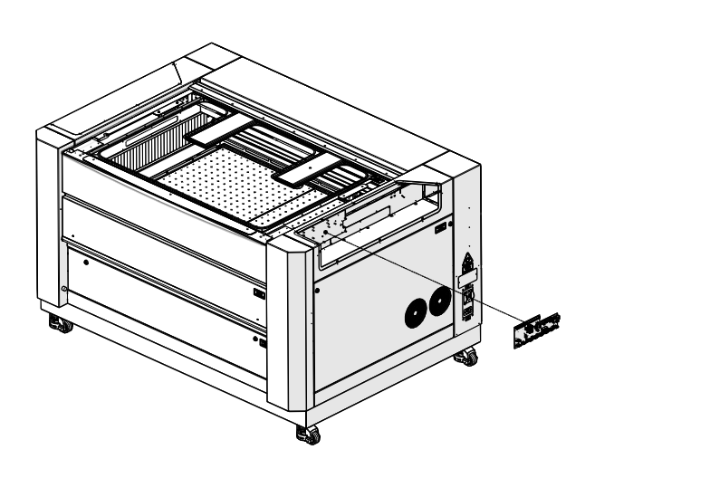
Loosen and remove the sixteen Phillips screws on the backplane board (circled in red).
Remove Backplane Board
Remove the backplane board from the engraver.
Backplane Board Installation
Put On Anti-Static Strap
Place the anti-static strap around your wrist and attach the clamp to a bare metal surface on the engraver.
Install Backplane Board
Place the new CS0348 backplane board into the engraver.
Install Board Screws
Install and tighten the sixteen Phillips screws that secure the board (circled in red).
Connect Harnesses
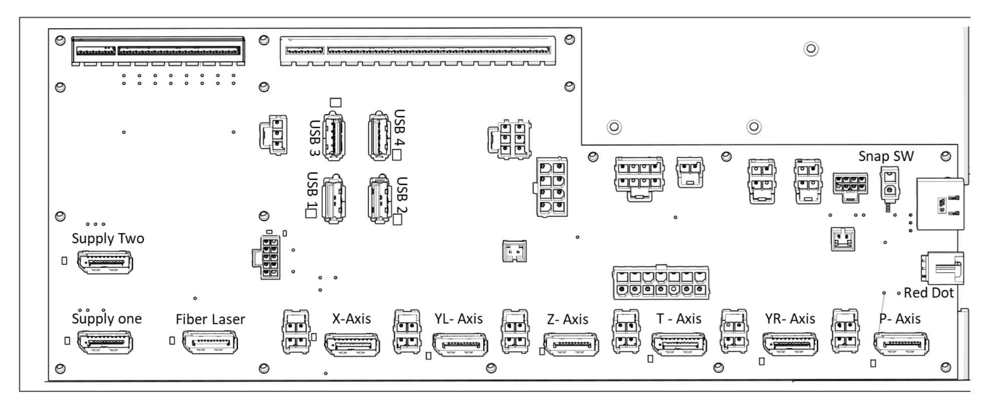
Reconnect the electrical harnesses to the backplane board. Use the connector map below, or your photo, to match each harness to its receptacle.
Backplane Connector Map
Labeled view of the backplane board receptacles.
Install Fan Tray
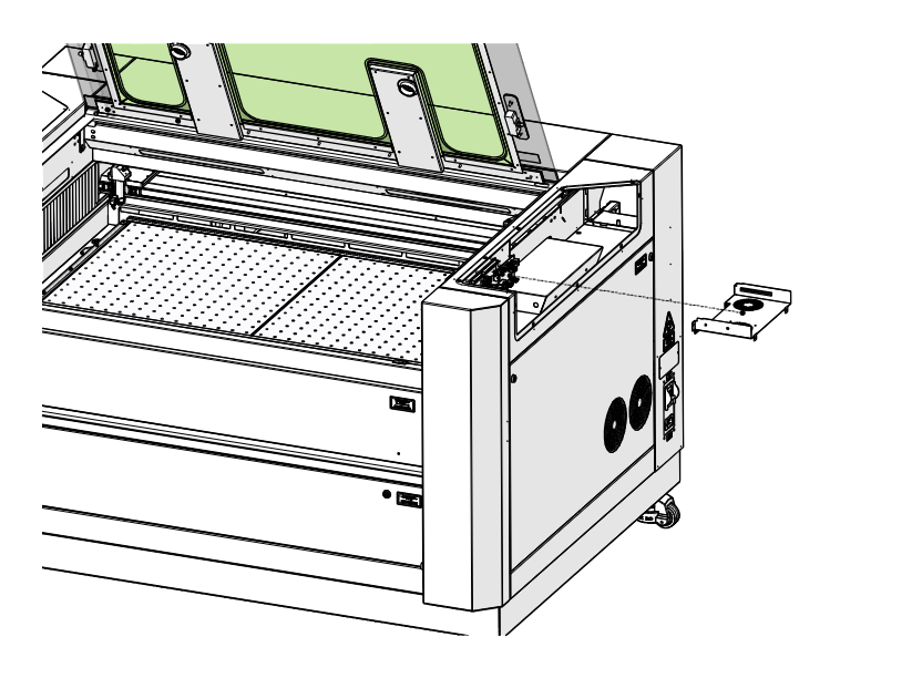
Install the fan tray.
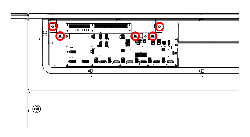
Install Fan Tray Screws
Install and tighten the five Phillips screws that secure the fan tray (circled in red).
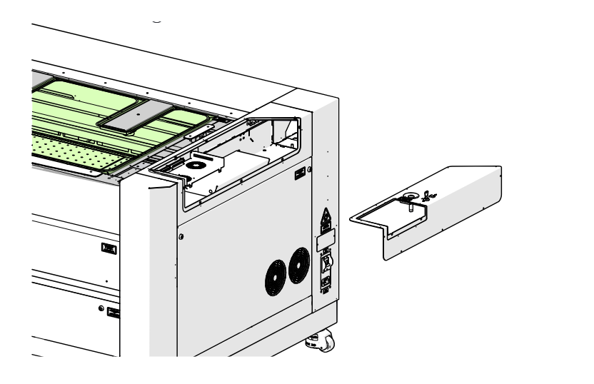
Place Corner Panel
Place the upper right corner panel on the engraver.
Connect Key Switch and E-Stop
Reconnect the key switch and emergency stop harnesses (circled in red).
Install Corner Panel Screws
Install and tighten the nine T8 Torx screws on the corner panel (circled in red).
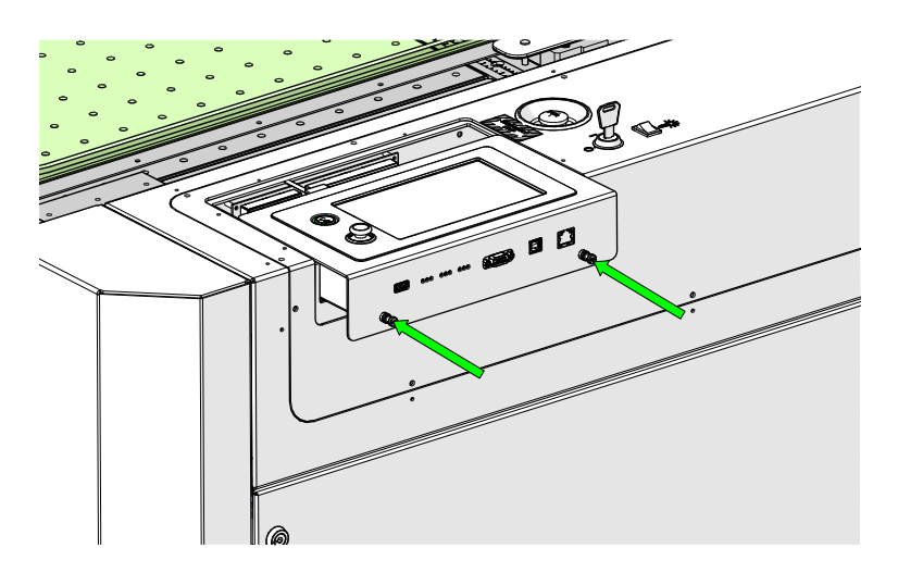
Install Control Module
Set the sides of the control module in the tracks on the housing and gently slide it in.
Tighten Control Module Screws
Tighten the two Phillips screws on the control module (circled in red).
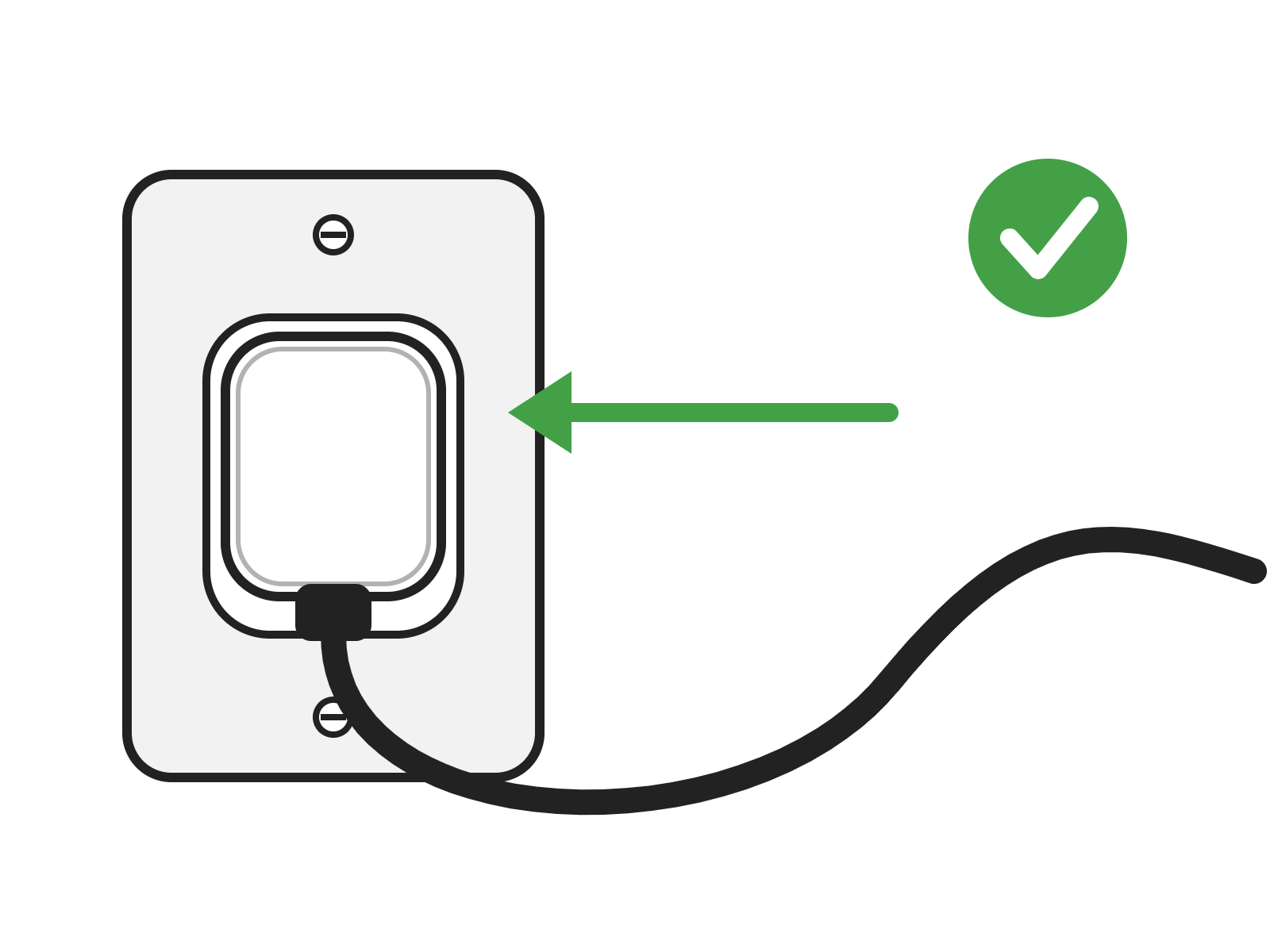
Power On
Reconnect the engraver to power and turn it on.
Program the Backplane Board
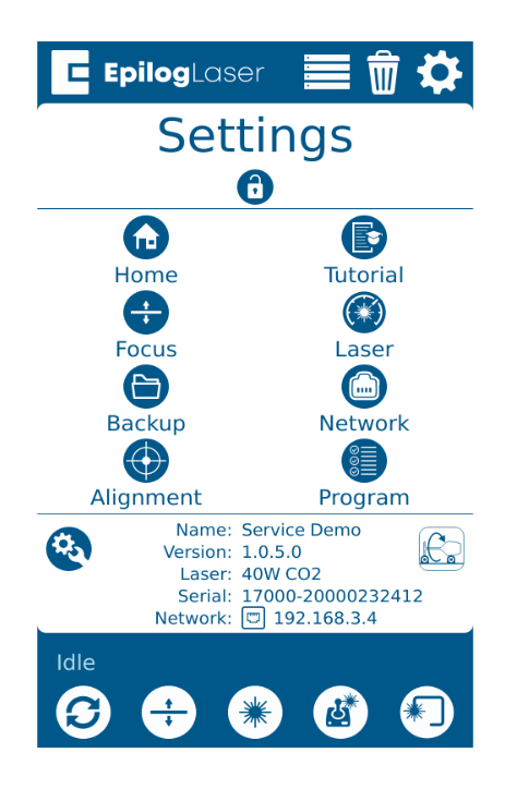
Open the Program Menu
On the display, press the gear icon in the upper right corner to open the Settings menu, then press Program to open the Peripheral Update menu.
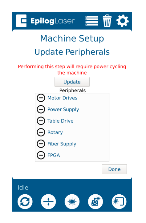
Update All Peripherals
Select all of the available components and press Update.
Restart When Prompted
Let the engraver run the update. When it prompts you to restart, power cycle the engraver.
Important: Do not power off the engraver during the update. It is normal for the display to turn off while the update runs.