This guide covers reseating the X-axis, Y-axis and control board connections on the Epilog Fusion Pro. A loose or partially seated connector can cause motion, homing and communication problems, so reseating is a common first step when troubleshooting. Only reseat the connections Epilog Technical Support has asked you to check.
Parts Required
- None
Tools / Materials Required
- 5/32″ Allen Wrench
- Phillips Screwdriver
- Canned Air
- Microfiber Cloth
- Tape (optional)
Safety First: Ensure the engraver is completely powered off and the power cord is disconnected before removing any panels or touching internal electronics.
Note: Reseat only the connections related to your current issue. If you have not been told which connections to reseat, contact the technician who sent you this article before starting. Reseating a connection that is working risks damaging the connector or seating it improperly.
X-Axis Connections
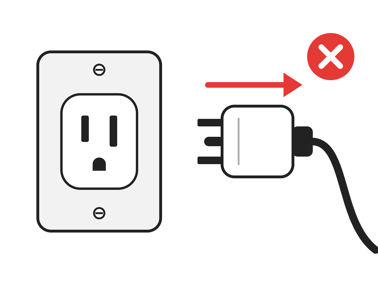
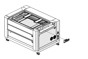
Power Off and Position the Arm
Turn off the engraver and unplug the power cord. Move the X-axis arm about halfway forward in the machine.
Remove the Right Side Panel
Remove the blue panel on the right side of the machine (the side with the fans). Turn the two 5/32″ Allen lock screws at the top of the panel 90° counterclockwise, then lift the panel off.
Remove the X-Axis Board Cover
On the right end of the arm you will see the X-axis motor and its circuit board, covered by a metal cover. Loosen the four Phillips screws (two on the left, two on the right) slightly, then slide the cover off.
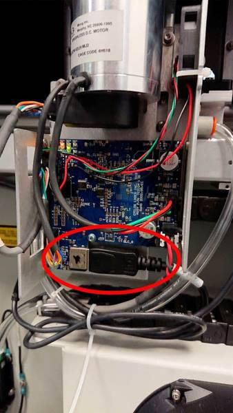
Reseat the X-Axis Data Connector
Locate the data connector on the X-axis board (circled in red). Press in the clip on the front of the connector and pull the connector to the right to unplug it. Plug it back in and make sure it is fully seated.
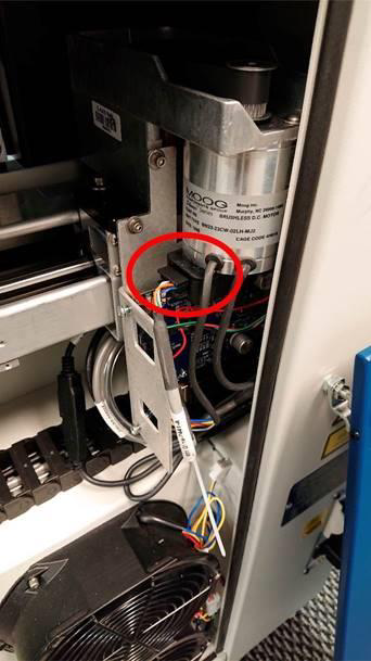
Reseat the X-Axis Encoder Connector
Locate the encoder connector on the motor (circled in red). Squeeze the top and bottom of the connector to unlock it and pull it to the left to unplug it. Plug it back in, pressing firmly.
Note: This connector can take a fair amount of force to seat fully. Push until it is completely in.
Reinstall the Cover and Side Panel
Slide the X-axis board cover back on and tighten its four screws. Reinstall the right side panel and turn the two lock screws 90° clockwise to secure it.
Y-Axis Connections
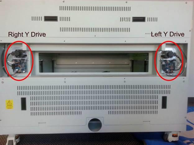
Remove the Back Panel
Remove the 5/32″ Allen screws holding the lower back panel (8 or 10, depending on machine size) and take the panel off. This exposes the right and left Y drives (circled in red).
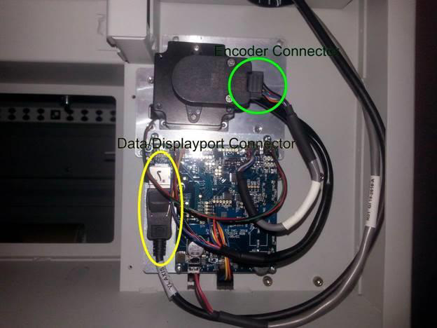
Reseat the Y-Axis Encoder Connector
On each Y drive, locate the motor encoder connector (circled in green). Press in the clip and unplug it, then plug it back in, pressing hard to make sure it goes in all the way.
Note: These connectors can be stiff to remove and install, and may take a fair amount of force to seat fully.
Reseat the Y-Axis Data Connector
Locate the DisplayPort-style data connector (circled in yellow). Press in its locking clip, as with the X-axis data connector, and unplug it. Plug it back in and make sure it is pushed completely up and into place.
Reinstall the Back Panel
Put the back panel back on and reinstall its 5/32″ Allen screws.
Control Board Reseating
Confirm Power Is Disconnected
Before you start, confirm the engraver is turned off and the power cord is unplugged.
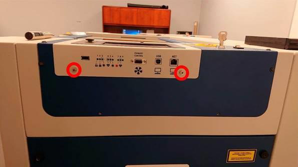
Slide Out the Control Board
Loosen the two screws on the control board faceplate (circled in red) as far as they will go. Pull on them to slide the control board out, and set it display side down on the top glass of the machine.
Remove the Blue Panel
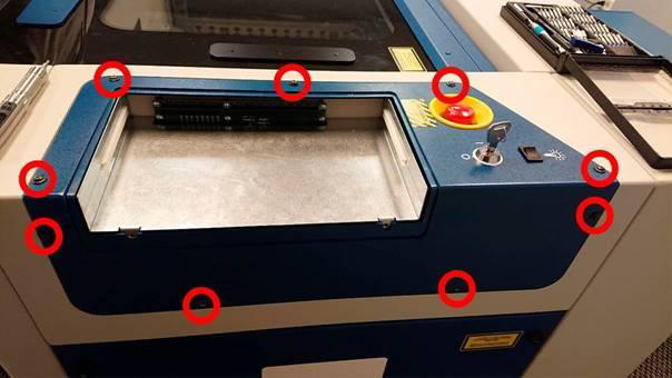
Remove the nine screws (circled in red) holding the blue panel around the control board slot. Wires are still attached to the panel, so lift it up and rotate it to the right, then set it on top of the machine.
Reseat the Backplane Connections
With the panel off, you can see the underside of the backplane board that the control board plugs into. Its connectors are all labeled. Unplug and reconnect only the connections related to your current issue, making sure each one is fully seated.
Caution: If you were not told which connections to reseat, contact Epilog Technical Support before going further. Reseating every connection is not needed and risks damaging or improperly seating one that was working.
Reinstall the Blue Panel
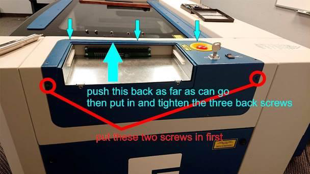
Set the blue panel back in place and install only the two lower screws (circled in red) first. Push the panel back toward the machine’s window as far as it will go (large arrow), and while holding it there, install and tighten the three back screws (small arrows). Then install the remaining screws.
Clean the Connector and Board Pins
Use canned air to blow out the black connector the control board plugs into. Then wipe the pins on the control board with a microfiber cloth to remove any dust or debris.
Note: Do not use a paper towel or similar material. It can leave lint and dust behind and cause more problems.
Reinstall the Control Board
Slide the control board back in along the plastic guides on the left and right of the slot. It should go in easily. Tighten the two faceplate screws.
If the board is hard to insert: remove it and repeat Steps 15–17. If it still feels wrong, or it “rides” up or down as it connects, contact Epilog Technical Support about adjusting the backplane.
Connect to Power
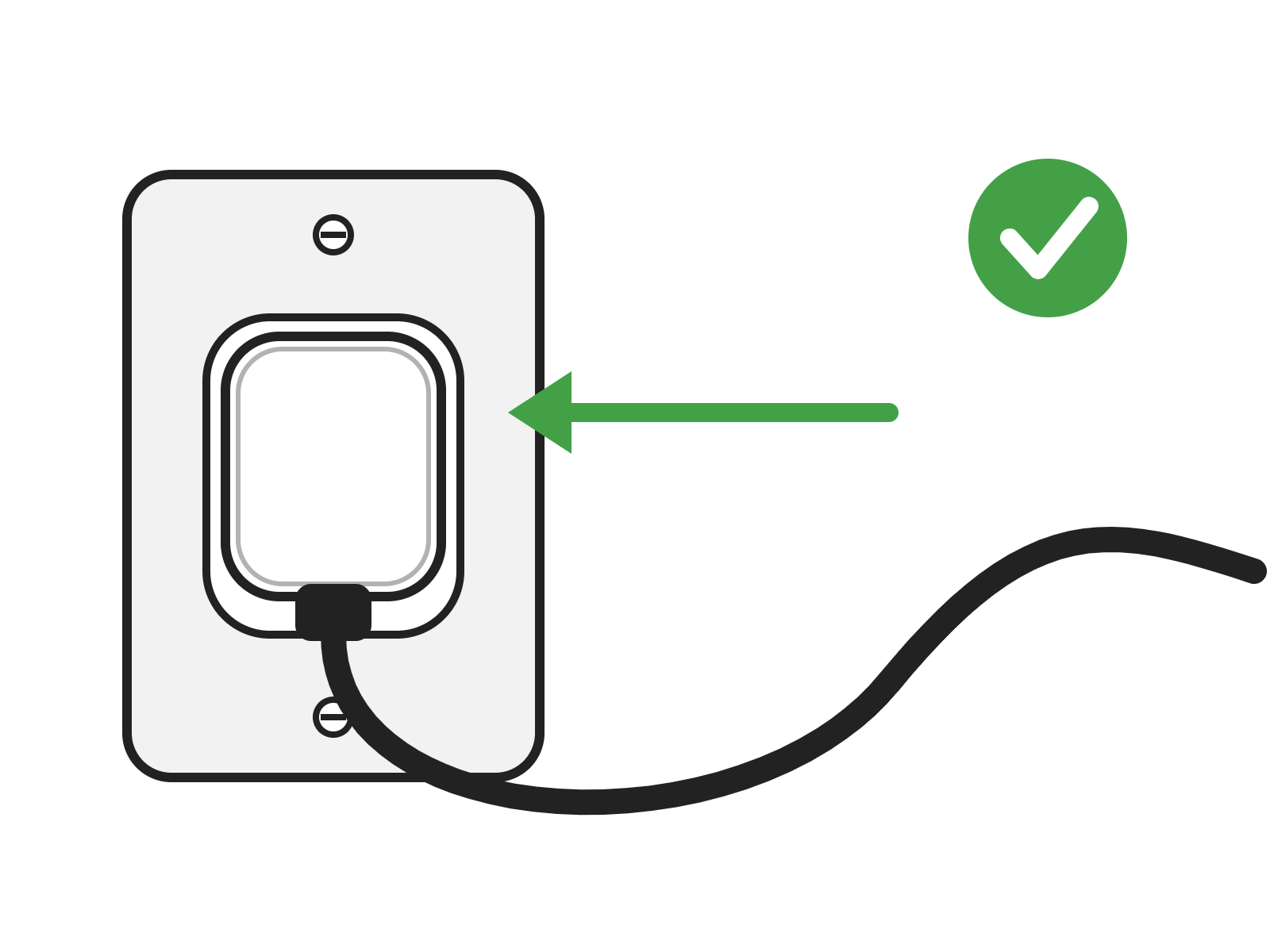
Plug the power cord back in and turn on the engraver.
Final Verification
Let the engraver home and run a test job to confirm the issue is resolved. If the problem continues, contact Epilog Technical Support.