The LC1000-TS main control board is the central processing unit for Epilog Fusion Edge, Maker, and Pro 24 / 36 laser systems. If the machine fails to power on, exhibits unresponsive startup behavior, is physically damaged, or diagnostic LEDs indicate a board-level issue, this checklist will help you determine whether the LC1000-TS board requires replacement. Follow the steps below in order, verifying each condition before proceeding. Before beginning, ensure the system is running the latest firmware version and that all connections are secure.
Diagnostic Wizard
Step 1: Confirm System Power
Power ON the machine.
Does the display illuminate?
(This typically takes 1-2 minutes)
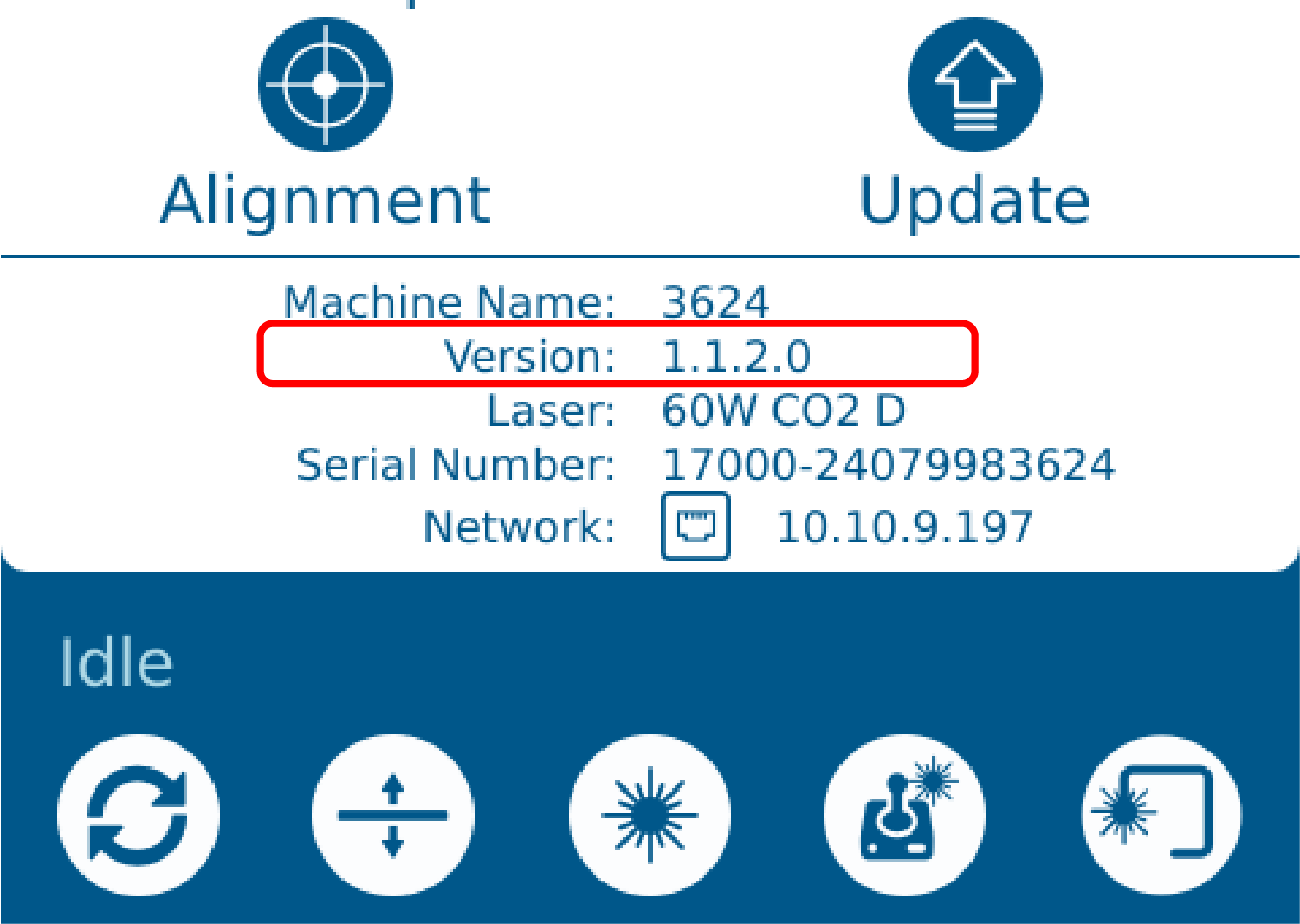
Step 2: Check Installed Firmware Version
Determine if the firmware currently installed on the machine is the latest available version.
-
How to Locate Your Current Firmware Version
-
On the touchscreen, tap the gear icon in the top-right corner.
-
The firmware version is shown at the bottom of the screen under Version:
-
-
View the Latest Firmware Version
-
The firmware version is shown at the bottom of the site under the “Current Firmware Details” header.
-
Does the firmware version match the latest version listed on our site?
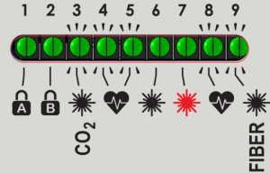
Step 2: Inspect LEDs
Inspect the LED indicators on the control board:
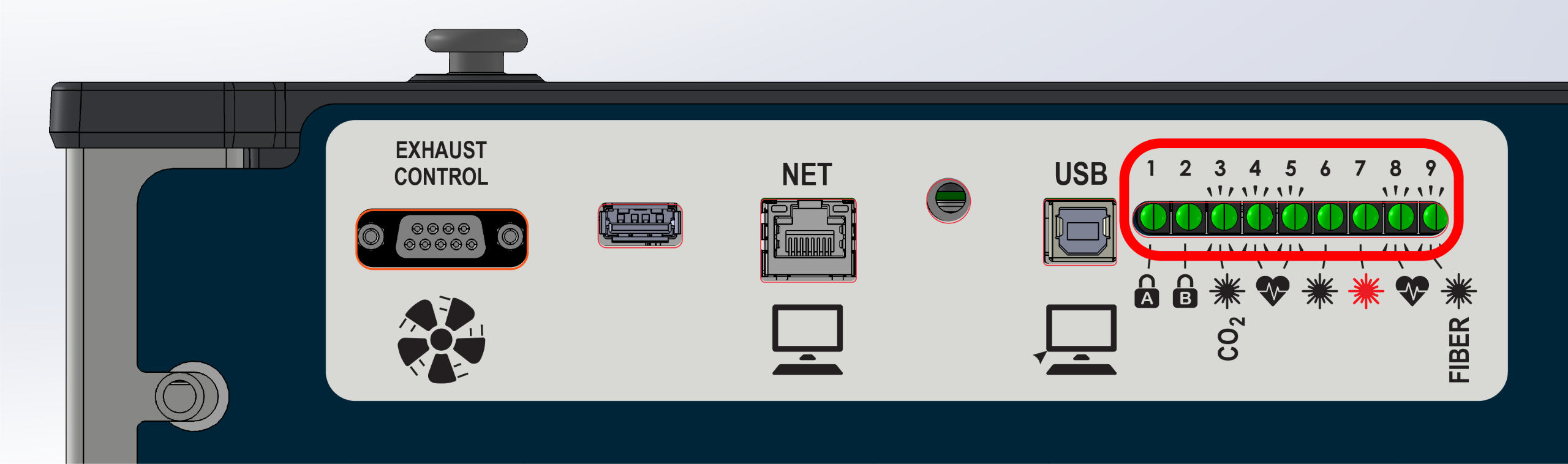
Are any of the LEDs illuminated or blinking?
Step 3: Check For LED #4 Heartbeat
Check the LED #4 status light on the right-side of the control board.
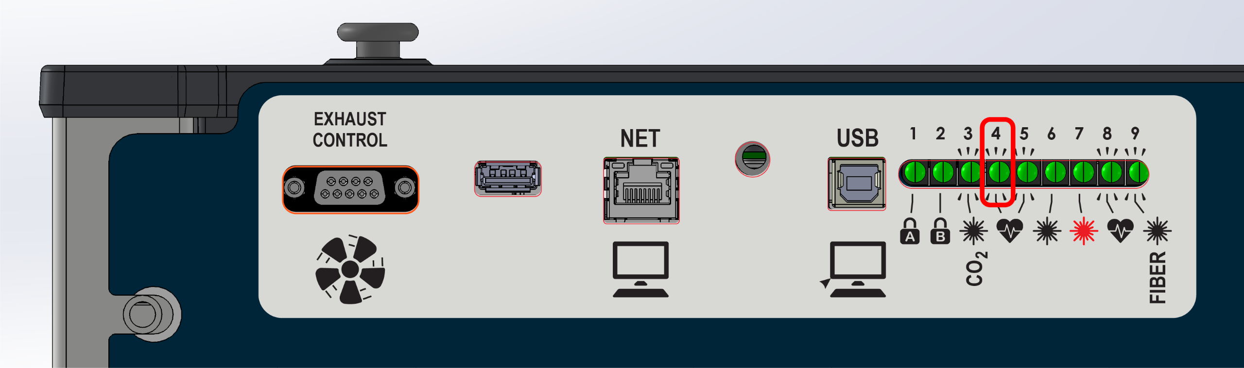
LED #4 should blink on and off like a heartbeat.
Is it blinking?
Step 3: Check Cabinet Lighting
Open the top door, check if the internal cabinet lighting is illuminated.
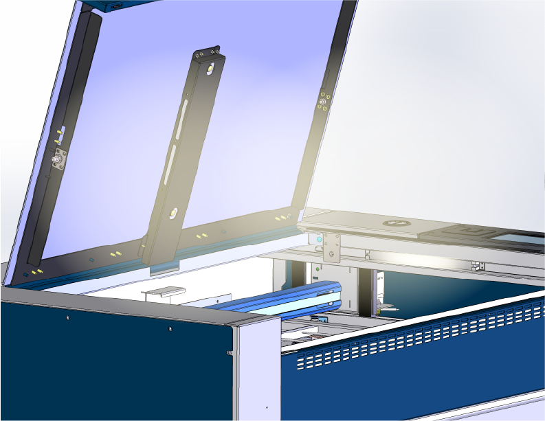
Is the cabinet lighting on?
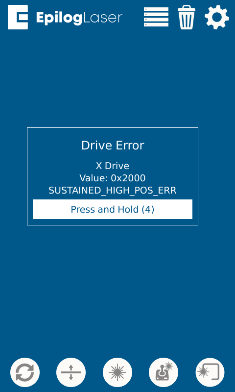
Step 3: Error Messages
Is there an error message displayed on the screen?
Example:
Step 4: Disconnect Components
If the cabinet lighting is on, but there are no LEDs illuminated on the control board, disconnecting 48v components can help isolate the issue.
- Power OFF the machine and disconnect the power cable.
Warning: The following steps involve disconnecting electrical harnessing. The power must be disconnected before proceeding.
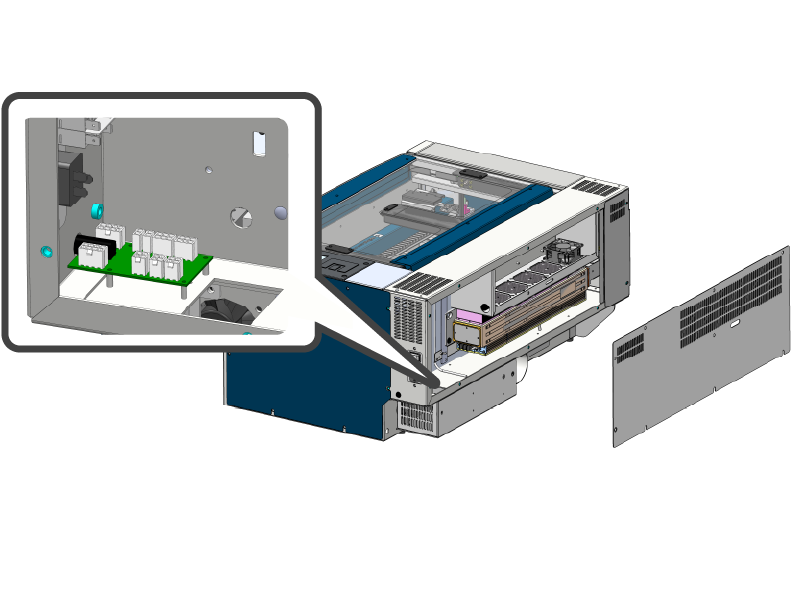
- Locate the 48v breakout board.
-
48v Breakout Board Location Images
24×12 Machines
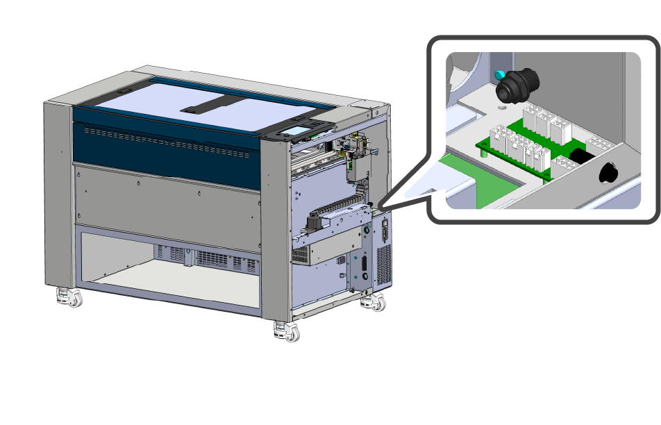
24 / 36 Machines
-
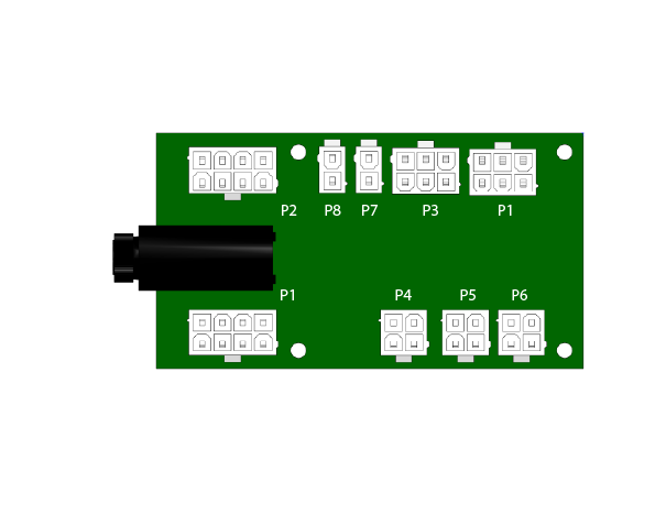
- Disconnect the components outlined below.
-
LC0812 Breakout Board
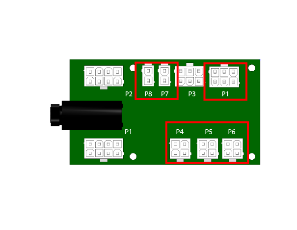 Note: There may not be connections to all of these ports. Uplug the harnesses available in these positions.
-
- Reconnect the power cable and power ON the machine.
Does the display illuminate?
(This typically takes 1-2 minutes)
Step 4: Incoming Power
If the cabinet lighting is off, the machine may not be receiving power.
- Power OFF the machine.
- Verify that the machine is plugged in and the outlet is functional.
Is the outlet funtional, and the cable secure?
Step 4: Clearing Error Messages
Some error messages require you to press and hold for several seconds to clear the error.
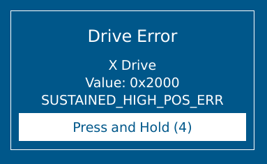
Can the error be cleared?
Step 4: Check SD Card
If LED #4 is off, or not blinking correctly, the SD card may be damaged.
- Ensure the SD card is properly installed in the LC1000-TS board.
- Reflash the SD card with the latest firmware.
- Replace the SD card.
Step 4: Proper Boot Sequence
When the machine powers ON, it should attempt the boot sequence:
- Table moves downward
- Rail moves to back of machine
- Lens carriage moves left
Does the machine attempt to complete the boot sequence?
Step 4: Frozen Display
Is the display stuck on a solid black, red, or white screen?

Step 5: Select Machine Wattage / Type
Select your machine wattage / type.
Low Watt / Fiber Only
- 30 Watt CO2
- 40 Watt CO2
- Fiber Only Machine
High Watt
- 50 – 200 Watt CO2
- Dual Source Pro
Step: 5: Repair Incoming Power
If the outlet is not functional, you must repair the outlet or use another functional outlet.
- Check with electrician.
- Repair or replace outlet.
If the machines power cable is broken or damaged, reach out to Epilog Support or Epilog Shop for a replacement.
Step 5: Proper Boot Sequence
When the machine powers on, it should attempt the boot sequence:
- Table moves downward
- Rail moves to back of machine
- Lens carriage moves left
Does the machine attempt the boot sequence?
Step 5: Check For LED #4 Heartbeat
After flashing or replacing the SD card, power on the machine and check for LED #4 heartbeat:
LED #4 should blink on and off like a heartbeat.
Is it blinking?
Step 5: Check SD Card
The SD card may be damaged.
- Ensure the SD card is properly installed in the LC1000-TS board.
- Reflash the SD card with the latest firmware.
- Replace the SD card.
Step 5: Collect Logs / Troubleshoot Error
After clearing the error, collect the machine logs.
Click the “Generating Machine Logs” button below to see the article on collecting logs.
Once you have collected the logs, submit a ticket to have support review them.
Diagnosis: More information is needed to determine the root cause.
Step 5: Touchscreen Behavior
The touchscreen should respond to touch and allow navigation through menus and settings.
Is the display responding to touch correctly?
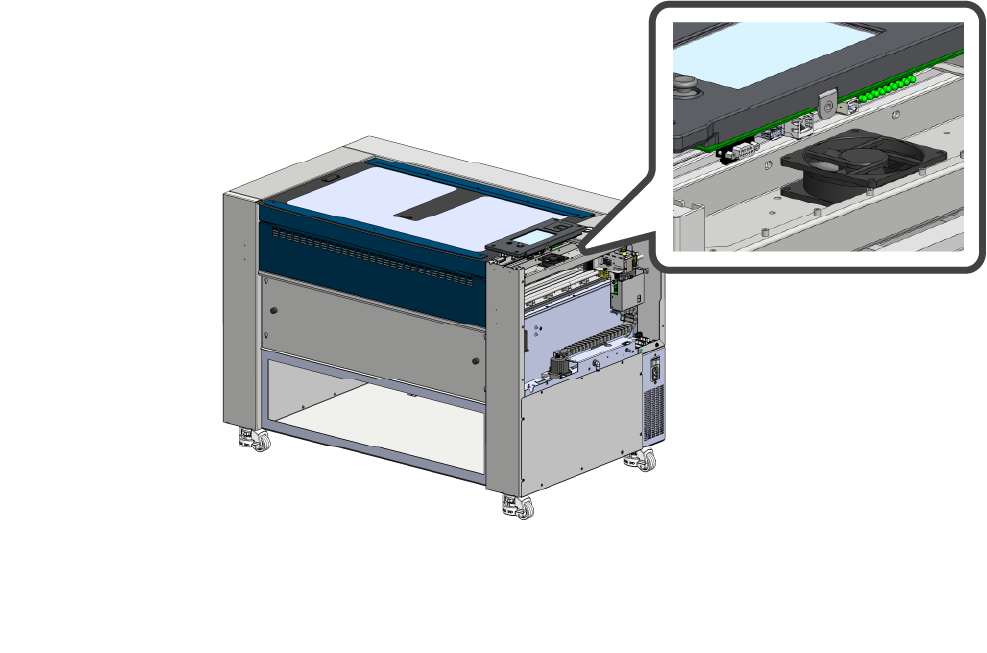
Step 5: Frozen Display
If the display is frozen , it may be due to a software issue or hardware problem.
- Check that the fan under the control board is operational.
- Replace the fan if it’s not spinning.
- Collect machine logs if possible.
- Check that the SD card is properly installed.
- Flash or replace the SD card.
After completing the recommendations above, has the behavior of the machine changed?
Step 5: Disconnect Components
The control board may be shorted, disconnecting components can help isolate the issue.
- Power OFF and diconnect the machine from power.
Warning: The following steps involve disconnecting electrical connections from the control board. The power must be disconnected before proceeding.
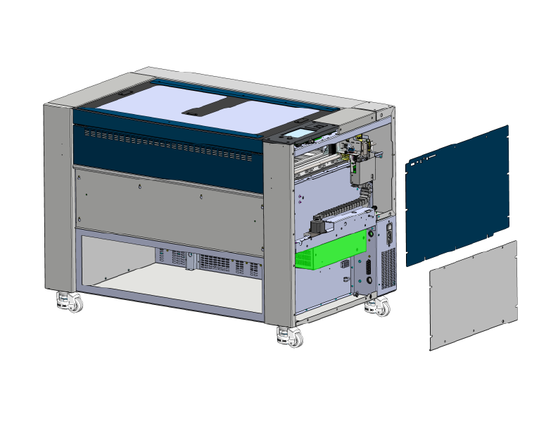
- Remove the right-side panel.
- Remove the screws securing the control board
-
Control Board Removal Images
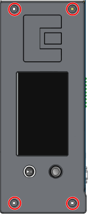
LC1000-TS
-
- Carefully lift the control board to access the harnesses underneath
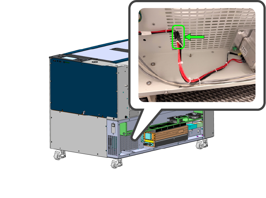
- Disconnect everything except the harness highlighted below (48v to control board).
Note: For Pro models, the backplane will need to be bypassed to make this connection. The ports and control boards are identical.
-
48v Connection Images
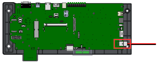
48v connection to LC1000-TS
-
- Reconnect the power cable, and power ON the machine.
Does the display illuminate?
Step 5: Check SD Card
The SD card may be damaged.
- Ensure the SD card is properly installed in the LC1000-TS board.
- Reflash the SD card with the latest firmware.
- Replace the SD card.
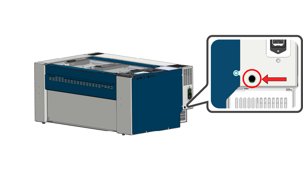
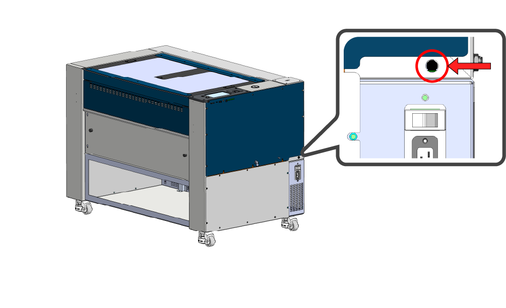
Step 6: Check Power Supply LED
Verify the power supply LED is illuminated.
- Locate the power supply.
-
Power Supply Location Images
24×12 Machines
24 / 36 Machines
-
- Power ON the machine
- Look through the vent for a green LED on the power supply
-
Power Supply LED Images
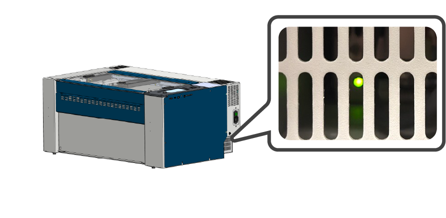
24×12 Machines
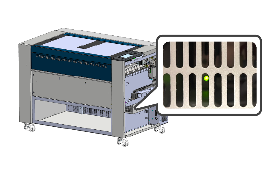
24 / 36 Machines
-
Is the power supply LED on?
Step 6: Check Power Supply LED
Verify the power supply LED is ON.
- Locate the power supply.
-
Power Supply Location Images
24×12 Machines
24 / 36 Machines
-
- Power on the machine
- Look through the vent for a green LED on the power supply
-
Power Supply LED Images
24×12 Machines
24 / 36 Machines
-
Is the power supply LED on?
Step 6: Proper Boot Sequence
When the machine powers ON, it should attempt the boot sequence:
- Table moves downward
- Rail moves to back of machine
- Lens carriage moves left
Does the machine attempt the boot sequence?
Step 6: Disconnect Components
The control board may be shorted, disconnecting components can help isolate the issue.
- Power OFF and diconnect the machine from power.
Warning: The following steps involve disconnecting electrical connections from the control board. The power must be disconnected before proceeding.
- Remove the right-side panel.
- Remove the screws securing the control board
-
Control Board Removal Images
LC1000-TS
-
- Carefully lift the control board to access the harnesses underneath
- Disconnect everything except the harness highlighted below (48v to control board).
Note: For Pro models, the backplane will need to be bypassed to make this connection. The ports and control boards are identical.
-
48v Connection Images
48v Connection to LC1000-TS
-
- Reconnect the power cable, and power ON the machine.
Does the display illuminate?
Step 6: Calibrate Touchscreen
- Click the gear in the top-right corner.
- Long press the title Settings.
- Press Test Display.
- Press Calibrate Display.
- Follow the on-screen prompts to complete touchscreen calibration.
After calibrating, is the touchscreen responding correctly?
Step 6: Verification
After flashing or replacing the SD card, have any of these condition changed:
- Attempted boot sequence.
- LED #4 behavior.
- Display illumination.
Has the behavior of the machine changed after flashing or replacing the SD card?
Step 7: Power Input
Check the fuse on the power input assembly.
- Power OFF the machine.
- Locate the fuse near the power cable input.
- Test or replace this fuse. There is a backup fuse in the assembly.
- If the fuse is verified good, replace the power input assembly.
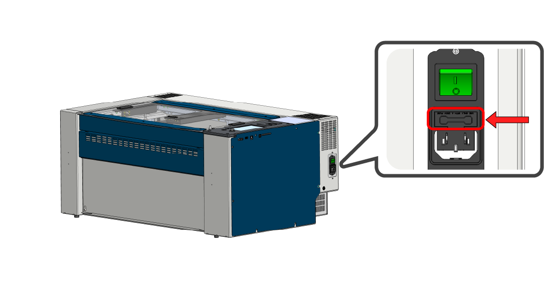
Outcome: Replace the fuse and or power input assembly.
Step 7: Power switch
Does the power switch “click” when you turn the machine ON? If not, the switch may be damaged, stuck, or broken. If a faulty switch is suspected, replace it and proceed.
- Check Power Switch
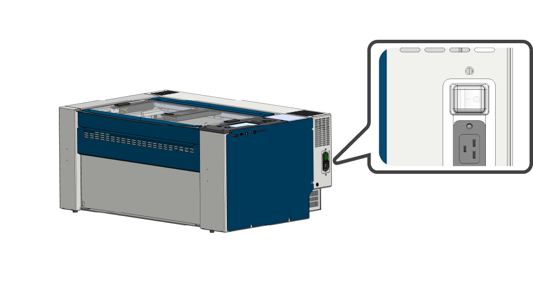
- Test or replace
Outcome: Replace the switch if a problem is suspected, otherwise continue.
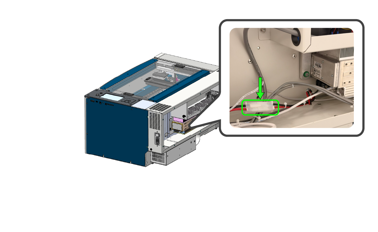
Step 7: Fuse on Breakout
If the light on the power supply is ON, but the cabinet lighting is OFF, then you should check the fuse on the 48v breakout board.
- Power OFF the machine.
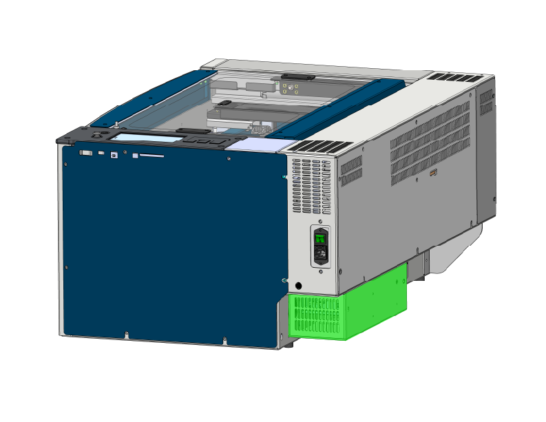
- Locate fuse on lower right side of machine.
-
Fuse Location Images
24×12 Machines
24 / 36 Machines
-
- If you can test the fuse and it’s functional, replace the LC0812 48v breakout board.
-
48v Breakout Board Location Images
24×12 Machines
24 / 36 Machines
-
- If you’re unable to test the fuse, replace the fuse first.
Outcome: Replace the fuse and or 48v breakout board LC0812.
Did replacing the fuse or breakout board change the behavior of the machine?
Step 8: Power Supply LED
If you’ve replaced a fuse, power input assembly, or power switch, power ON the machine and check the LED on the power supply.
Is there an LED illuminated on the power supply?
Step 8: Power Supply LED
If you’ve replaced a fuse, power input assembly, or power switch, power on the machine and check the LED on the power supply.
Is there an LED illuminated on the power supply?
Step 8: Disconnect Components
If after replacing the 48v breakout board and fuse, the cabinet lights and display still do not illuminate:
- Power OFF the machine and disconnect the power cable.
Warning: The following steps involve disconnecting electrical harnessing. The power must be disconnected before proceeding.
- Locate the 48v breakout board.
-
48v Breakout Board Location Images
24×12 Machines
24 / 36 Machines
-
- Disconnect the components outlined below.
-
LC0812 Breakout Board
Note: There may not be connections to all of these ports. Uplug the harnesses available in these positions.
-
- Reconnect the power cable, and power ON the machine.
Does the display illuminate?
(This typically takes 1-2 minutes)
Step 9: Disconnect Components
The power supply may be shorted, disconnecting 48v components can help isolate the issue.
- Power OFF the machine and disconnect the power cable.
Warning: The following steps involve disconnecting electrical harnessing. The power must be disconnected before proceeding.
- Locate the 48v breakout board.
-
48v Breakout Board Location Images
24×12 Machines
24 / 36 Machines
-
- Disconnect all components from the breakout board.
- Reconnect the power cable and power ON the machine.
Is there an LED illuminated on the power supply?
Step 9: Disconnect Components
The control board may be shorted, disconnecting 3.3v components can help isolate the issue.
- Power OFF and diconnect the machine from power.
Warning: The following steps involve disconnecting electrical connections from the control board. The power must be disconnected before proceeding.
- Remove the right-side panel.
- Remove the screws securing the control board
-
Control Board Removal Images
LC1000-TS
-
- Carefully lift the control board to access the harnesses underneath
- Disconnect everything except the harness highlighted below (48v to control board).
Note: For Pro models, the backplane will need to be bypassed to make this connection. The ports and control boards are identical.
-
48v Connection Images
48v connection to LC1000-TS
-
- Reconnect the power cable, and power ON the machine.
Does the display illuminate?
Step 10: Disconnect Laser Tube
The laser tube may be shorting the power supply.
- Power OFF the machine and disconnect the power cable.
Warning: The following steps involve disconnecting electrical harnessing. The power must be disconnected before proceeding.
- Locate the laser tube harness.
-
Laser Harness Example Images
Connection Type 1
Connection Type 2
- Disconnect the laser tube harness.
Note: There are several types of laser tube harnesses. Follow the red and black wires from the laser tube to the connection point and disconnect the harness.
- Reconnect the power cable and power ON the machine.
Is there an LED illuminated on the power supply?
Diagnosis: Damaged Power Supply
Verify the conditions below.
- When powered ON, the display does not illuminate.
- There are no LEDs illuminated on the right-side of the control board.
- Cabinet lighting is OFF.
- The incoming power has been tested. The outlet and power cable are working.
- No LED on the Power Supply.
- The Power Input Assembly / Switch have been tested or replaced.
- Disconnecting 48v components didn’t change the behavior of the machine.
If all the conditions above are true, replace the power supply.
Outcome: Replace the Power Supply.
Diagnosis: Damaged Laser Tube or Wiring Harness
The laser tube or wiring harness may be shorting the power supply. Inspect the connection on the laser tube and it’s wiring harness for damage or loose connections.
- Inspect wiring harnesses for damage or loose connections.
- Replace the harnessing if damage is found.
If the wiring harnesses and connections are good, replace the laser tube.
Outcome: Replace the Laser Tube.
STOP : Update Firmware
Outcome: Download and install the latest firmware for your system from the Epilog support site.
Once the firmware has been installed, click the “start over” button below.
Action: Complete the peripheral update using the procedure below.
Next: Once you have completed the peripheral update click the continue button.
Diagnosis: Touchscreen Issue
If after flashing or replacing the SD card, the error persists, please submit a ticket to Epilog Support for further assistance.
Outcome: More information is needed to confirm the issue.
Diagnosis: Touchscreen Damaged
If the touchscreen is still not responding correctly after calibration, it may be damaged and require replacement.
Sometimes the calibration process is not being completed correctly. Please submit a ticket to Epilog Support for further assistance.
Outcome: More information is needed to confirm the issue.
Diagnosis: System is Functioning Properly
If the machine is booting up and the display is responsive, the LC1000-TS is most likely functioning properly.
If you suspect there is still an issue, click the button below to submit a ticket.
Diagnosis: Shorted Component
One or more of the disconnected components is shorting out the power supply, this component (or harnessing) need(s) to be isolated and replaced.
- Power the machine OFF.
Warning: The following steps involve disconnecting electrical harnessing. The power must be disconnected before proceeding.
- Reconnect one of the disconnected components to the 48v breakout board.
- Power the machine on.
- If the conditions don’t change, that is not the shorted component.
- Power OFF the machine.
- Reconnect one additional component to the 48v breakout board and power on the machine.
- Repeat this process, powering ON and OFF after each additional component is reconnected.
One of the components should cause the machine to exhibit the initial symptoms (ie. no display or LEDs), this is the component responsible for shorting the power supply. Power OFF the machine, check if the 48v breakout board fuse is blown. Then check the harnessing to the suspected component for damage, if no damage is found, replace the component and fuse if necessary.
Outcome: Isolate and replace the shorted component.
Diagnosis: Shorted Component
One or more of the disconnected components is shorting out the control board, this component (or harnessing) need(s) to be isolated and replaced.
- Power OFF the machine.
Warning: The following steps involve disconnecting electrical harnessing. The power must be disconnected before proceeding.
- Reconnect one of the disconnected components to the control board.
- Power the machine ON.
- If the display illuminates, that is not the shorted component.
- Power OFF the machine.
- Reconnect one additional component to the control board and power on the machine.
- Repeat this process, powering ON and OFF after each additional component is reconnected.
One of the components should cause the machine to exhibit the initial symptoms (ie. no display or LEDs), this is the component responsible for shorting the control board. Check the harnessing to that component for damage, if no damage is found, replace that component.
Outcome: Isolate and replace the shorted component or harnessing.
Diagnosis: LC1000-TS Control Board Damaged
Verify the following statements are true.
- The display does not illuminate when the machine is powered on.
- The SD card has been flashed or replaced.
- LED #4 does not blink on and off like a heartbeat with the machine on.
- Disconnecting components from the control board resulted in no change.
Outcome: Replace the LC1000-TS Control Board.
Diagnosis: LC1000-TS Control Board Damaged
Verify the following statements are true.
- Machine attempts to home.
- LED 4 blinks like heartbeat.
- Display is NOT illuminated.
- SD card has been Flashed / Replaced
Outcome: Backlit display may be damaged. Replace LC1000-TS Control Board
Diagnosis: LC1000-TS Control Board Damaged
Verify the following statements are true.
- Machine attempts to home.
- LED 4 blinks like heartbeat.
- Display is NOT illuminated.
Outcome: Backlit display may be damaged. Replace LC1000-TS Control Board
Diagnosis: LC1000-TS Control Board Damaged
Check the condition below.
- The display does not illuminate.
- LEDs on the control board do not illuminate.
- Cabinet lighting is OFF.
- Disconnecting components from the 48v breakout board changed nothing.
If all the conditions above are true, replace the LC1000-TS control board.
Outcome: Replace the LC1000-TS Control Board.
Diagnosis: LC1000-TS Control Board Damaged
Verify the following statements are true.
- The display does not illuminate when the machine is powered on.
- LEDs on the control board do not illuminate with the machine on.
- Cabinet lighting is on.
- Disconnecting components from the 48v breakout board resulted in no change.
If all the conditions above are true, replace the LC1000-TS control board.
Outcome: Replace the LC1000-TS Control Board.
Diagnosis: LC1000-TS Control Board Damaged
Verify the following statements are true.
- Machine does not attempt to home.
- LED 4 blinks like heartbeat.
- Display is NOT illuminated.
- SD card has been Flashed / Replaced.
If all the conditions above are true, replace the LC1000-TS control board.
Outcome: Replace the LC1000-TS control board.
Diagnosis: LC1000-TS Control Board Damaged
Verify the following statements are true.
- The display illuminates.
- There are no error messages on the display.
- The display is frozen on black / red / white screen.
- The fan under the display is spinning.
- The SD card has been flashed or replaced.
Outcome: Replace the LC1000-TS Control Board.