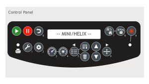
Keypad
The keypad on your laser system is the control panel for your machine. The easy-to-use control panel allows you to access your job, start and stop the laser, focus for your project, and much more. On the LCD panel you will see any current jobs at the machine. You can scroll through these jobs to the one you want to run.

Vector Cutting Grid
Here is the included vector-cutting grid for the Mini and Helix machines. This robust table with metal honeycomb grid allows you to cut through all kinds of materials with minimal backside burning.

Engraving Table
The cutting table can easily be removed and the engraving plate can be quickly installed for your engraving jobs. When you’re not vector cutting, the engraving task plate provides a level flat surface for optimal engraving quality across the entire work area of your laser system. The work area includes to two linear guide rulers that help with placement of your objects at the top left corner of the engraving table, and can also be used to hold down thin materials for cutting or engraving.


X-Axis Assembly
This is the I-Beam, or X-Axis Gantry. It will initially be parked in the upper location of your work area, so you have better access to the laser bed to place items on the table.

Lens Assembly
The laser’s lens assembly is carried on the I-Beam which moves left and right in a sweeping motion in the x-axis direction, and moves the lens carriage in the y-axis direction as well.

On the lens assembly you will find the industrial-grade mirrors, lens, auto-focus, and air assist tube. The mirrors and lens are rated to over 500 watts and are integral part of Epilog’s optics system. It consists of a mirror that reflects the laser beam down through a focal length lens. Keeping your laser optics clean will help them perform their best, and it starts with fully accessible front-mounted mirrors that can be easily removed for cleaning.
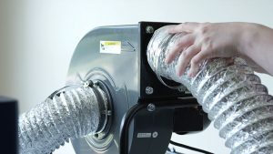
Air Assist
The Air Assist Tube directs a constant stream of compressed air along the cutting surface, reducing the possibility of flaming, scorching or charring when cutting through materials. The Air Assist Tube must be used in conjunction with a standard compressed air supply, or the optional stand-alone compressor offered by Epilog.

Automatic Focus Gauge
The spring-based automatic focus gauge can be used to bring your table and material to the correct focal height automatically with the click of a button in the Epilog Mini / Helix Driver.

Air Intake
Looking at the top of the system, just behind the hinges for the top access door, you’ll see six air intake holes for the laser’s heat-sync fans. The laser tube for your system is located below these fans, which make up the Super-Silent Fan System which operate a low 59 to 62 decibel range.

Exhaust
At the back of the laser system you will find the exhaust plenum. The top 4 slots within the work area cabinet are where the engraving area will be exhausted of all of the smoke, dust and debris resulting from your engraving and cutting. The bottom two holes in the tray below the cutting and engraving plates operate as a vacuum suction table, pulling the air through the bottom of the cutting table away from the surface of your engraving material.


Front Access Door
On the front of the Mini and Helix machines you’ll find the front access drop-down door. This safety-interlocked door allows you to easily place a tray of jigged parts and larger items on the table through the front of the system.


Power
On the left side of the system in the bottom left corner you’ll find the Main Power switch, two AC breakers and where your power cord is attached to the system.

System Rear
Moving on to the back of the laser system you will find a 4” exhaust plenum to which you’ll attach your exhaust fan or filtration system. Just to the right of the Exhaust Plenum is the anodized tag where you’ll find your serial number, which you will need if you find it necessary to contact technical support.


Also, located on the back of the machine are the Auxiliary port used for system diagnosis, the Ethernet and USB ports used to connect your laser system to a computer, and the Air Assist Tube plugin for your compressor pump.


Interior System Components
As we remove the right side panel of the system, we can see the inner workings of the machine. Here you will find the X-Axis Motor and Belt, Y-Axis Rail Assembly, Y-Axis Motor, Y-Axis Belt, Control Board, and the Z-Axis Table Motor.

Now we’ll move the back of the system with the back panel removed. The first thing you’ll notice near the top is the heart and soul of your laser machine, the CO2 laser tube. A Collimator for the system’s Radiance optics, is installed on the right of the tube for the Mini 24 and Helix system. The laser beam passes through this collimator to create a more even beam across the laser table, then is reflected off the mirror at the top of the enclosure and back to a mirror at the rear of the system before moving on to the laser beam assembly.


A single power supply is located to the right of the exhaust plenum for 30 and 40 watt laser tubes, and an additional power supply is installed to the left of the exhaust plenum for 50, 60, or 75 watt laser tubes.

This was a quick look at the inner workings of your Mini and Helix laser systems. Now it’s time to start engraving!
Mini/Helix Manual Download
To check out more of the Mini/Helix laser features and capabilities, download the Mini/Helix Laser Manual.