The control module on Epilog laser systems provides connection points and LED indicators that offer system status and control feedback. This guide outlines each port and indicator located on the right side of the machine.
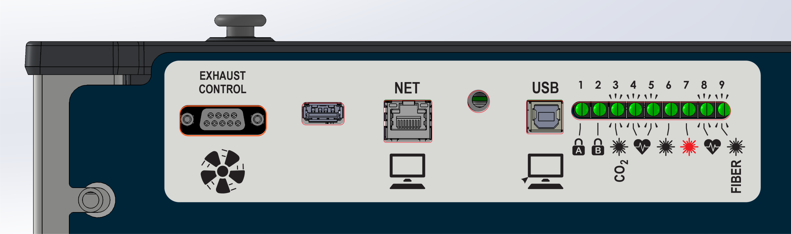
Port Descriptions
-
Exhaust Control: Connects to a compatible exhaust unit to send on/off commands.
-
USB Type-A: Used to update the firmware in the engraver.
-
Net: Connects the engraver to a computer via Ethernet (direct or networked).
-
USB Type-B: Used to connect the engraver to a computer via USB cable.
LED Indicators
-
1 – Interlock A: On when lid/door is shut; off when open.
-
2 – Interlock B: On when lid/door is shut; off when open.
-
3 – CO₂ Laser Control: On when the CO₂ laser is commanded to fire.
-
4 – Heartbeat: Blinks when the touchpad UI is active.
-
5 – Heartbeat: Blinks when the FPGA is active.
-
6 – CO₂ Laser Signal: On when receiving feedback from the installed CO₂ laser.
-
7 – Red Dot Pointer: On when the red dot pointer is enabled.
-
8 – Heartbeat: Blinks when motion control processor is active.
-
9 – Fiber: On when the fiber laser is commanded to fire.
Ascent-Specific Ports & Indicators
The Ascent system includes additional safety and control features not present on other models. These include a Class 4 enable dongle port and expanded interlock monitoring indicators.
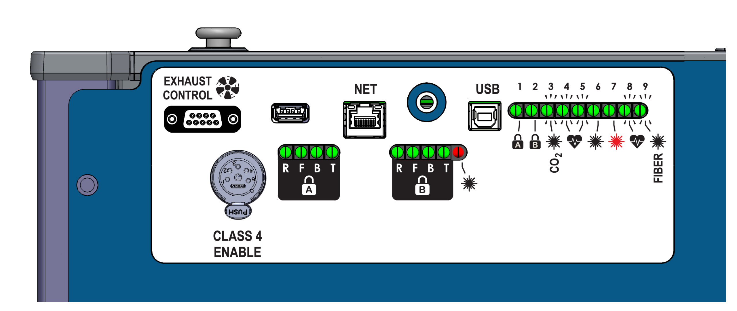
Additional Port
-
Class 4 Enable Dongle Port: This port accepts a hardware dongle required for Class 4 operation. When installed, the system allows operation with the front and rear drop-down doors open.
Additional LED Indicators
The Ascent board includes dual-channel interlock monitoring with detailed status LEDs for each safety input.
Channel A (Left-Side)
- R – Remote: Class 4 enable status.
- F – Front: Front interlock status.
- B – Back: Rear interlock status.
- T – Top: Top door status.
Channel B (Right-Side)
- R – Remote: Class 4 enable status.
- F – Front: Front interlock status.
- B – Back: Rear interlock status.
- T – Top: Top door status.
- CO2 Lasers: Illuminates when all required interlocks are met and the laser is enabled to fire.
- Fiber Lasers: Illuminates only when the laser is actively commaded to fire.
Behavior varies between Class 2 and Class 4 modes.
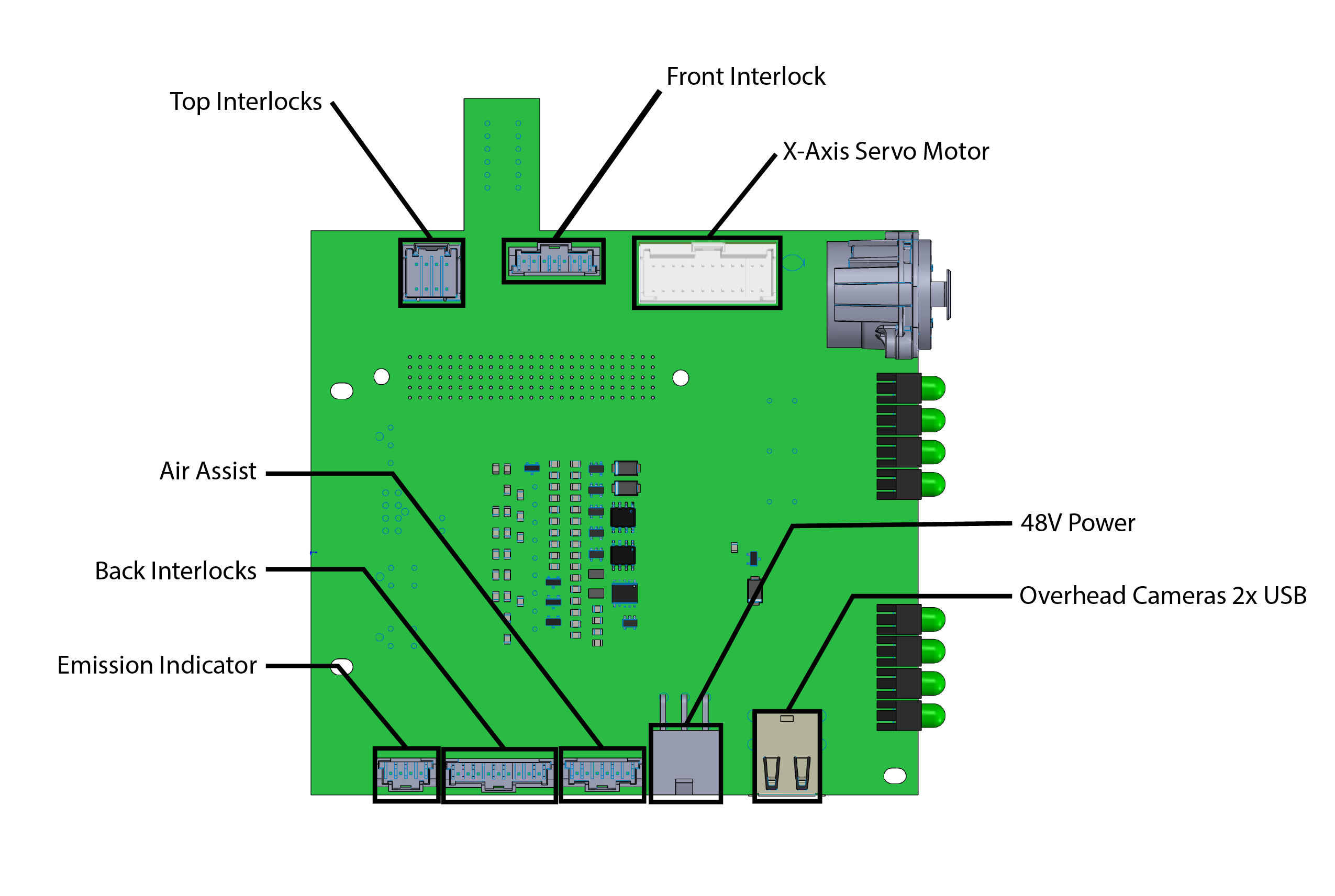
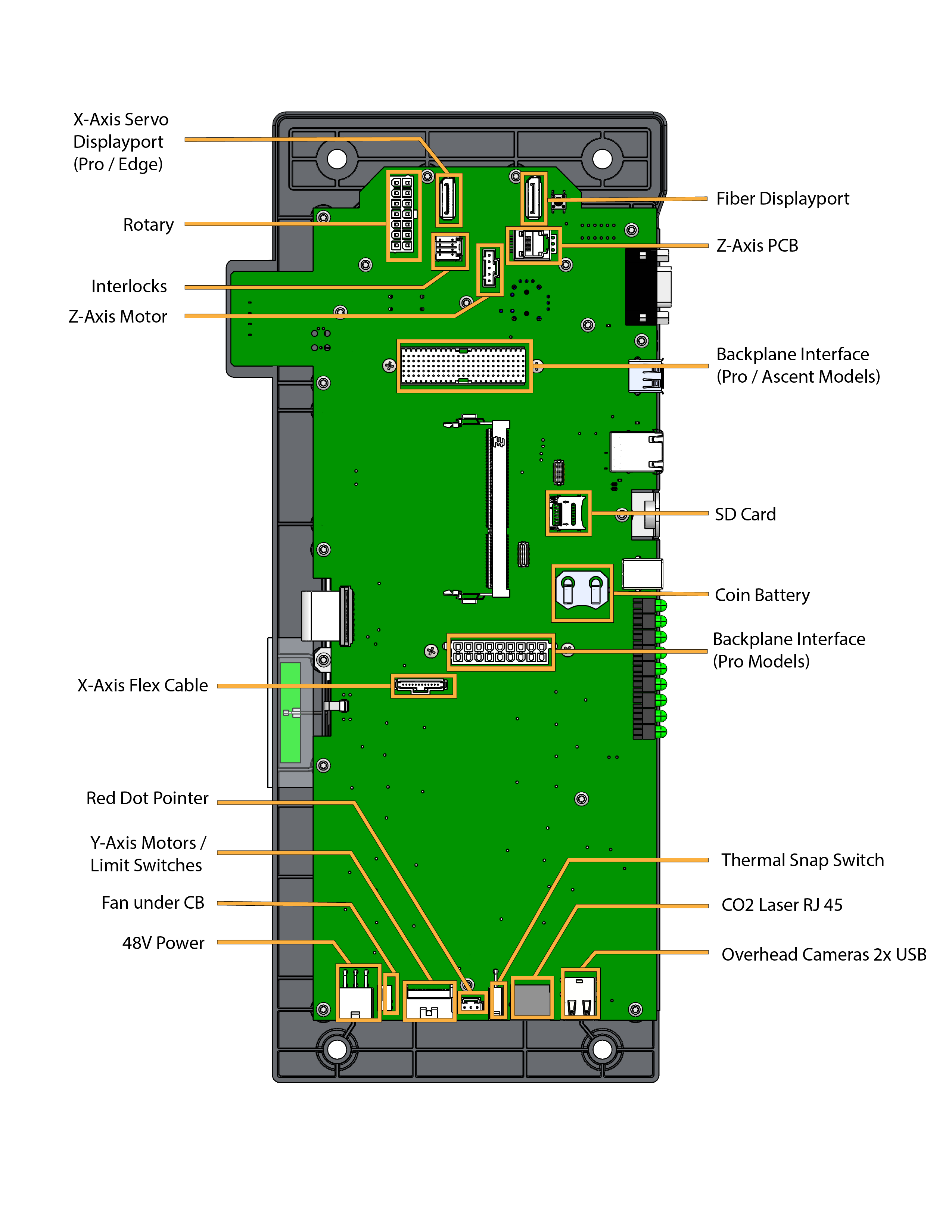
Board Components and Connections
LC1422 Backplane – Ascent