The control module is a crucial component of your Fusion Maker, Fusion Edge, or Fusion Pro engraver, enabling seamless operation and precise control. This guide provides step-by-step instructions for safely removing and installing a new control module to ensure optimal performance. Following these procedures will help you maintain your engraver’s efficiency and longevity.
Control Module Removal (Fusion Maker & Edge)
- Turn off the engraver.
- Disconnect engraver from power source.
- Disconnect the connection cables (USB, ethernet, fan control, etc.).
- Remove the right panel of the engraver.
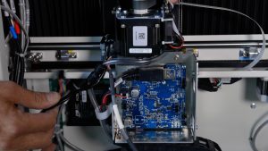
- Attach the anti-static strap to your wrist and clamp it to a bare metal surface.
-
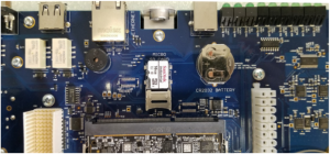
Loosen and remove the four (4) 5/32” Allen screws on the control module.
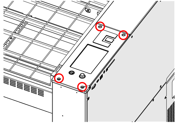
Note: Two (2) of the control module mounting screws are longer than the others. These longer screws secure the top side of the control module to the rear mounting locations.
-
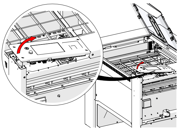
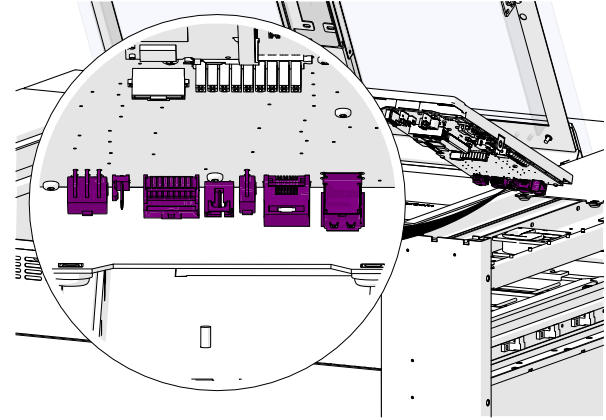
Gently raise the bottom of the control module to access the front electrical harnesses.
-
Disconnect the four (4) electrical harnesses.
-
Continue raising the module to access and disconnect the flex cable.
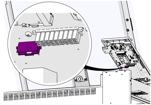
-
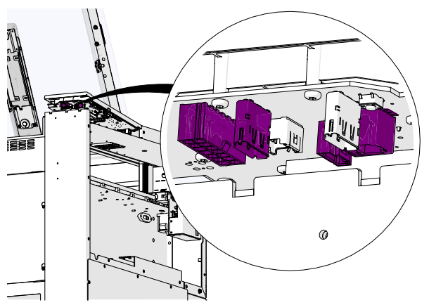
Disconnect the seven (7) rear electrical harnesses.
-
Remove the control module.
Control Module Installation (Fusion Maker & Edge)
- Attach the anti-static strap.
-
Place the control module in position.
-
Connect the seven (7) rear electrical harnesses.
-
Connect the flex cable.
-
Connect the four (4) front electrical harnesses.
Note: The X-Axis drive and fiber source receptacle both use a display port connector. Ensure that the display port cable is plugged in to the appropriate receptacle when reconnecting the front electrical harnesses.
-
Install and tighten the four (4) screws (ensure longer screws are in the rear).
- Reconnect power and turn on the engraver.
Programming the Control Module
-
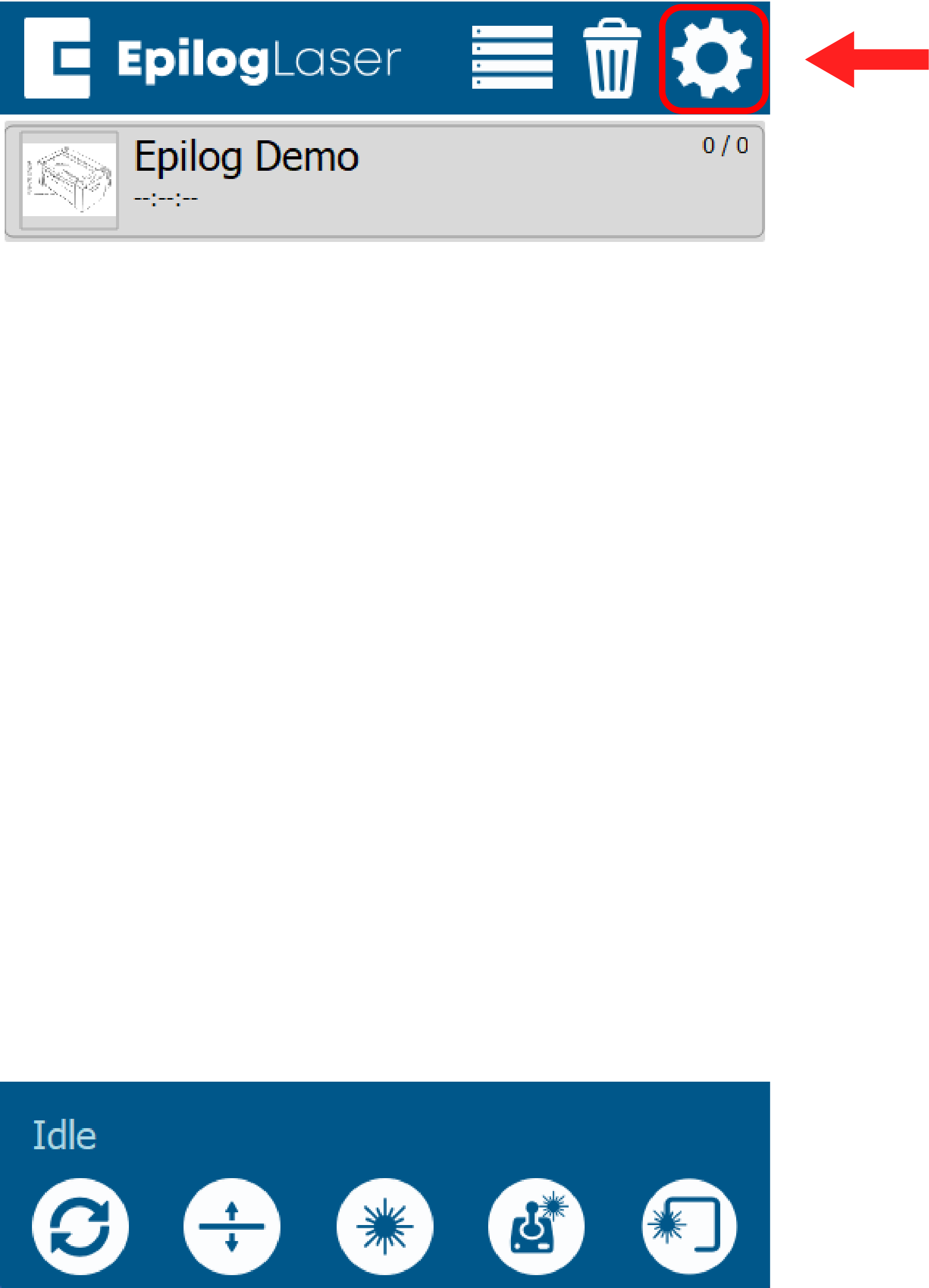
At the display panel, press the gear icon in the upper right-hand corner of the display to open the Settings menu:
-
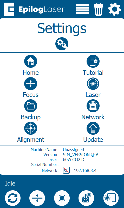
Press Update:
-
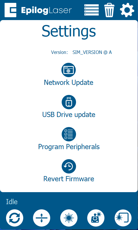
Press Program Peripherals
-
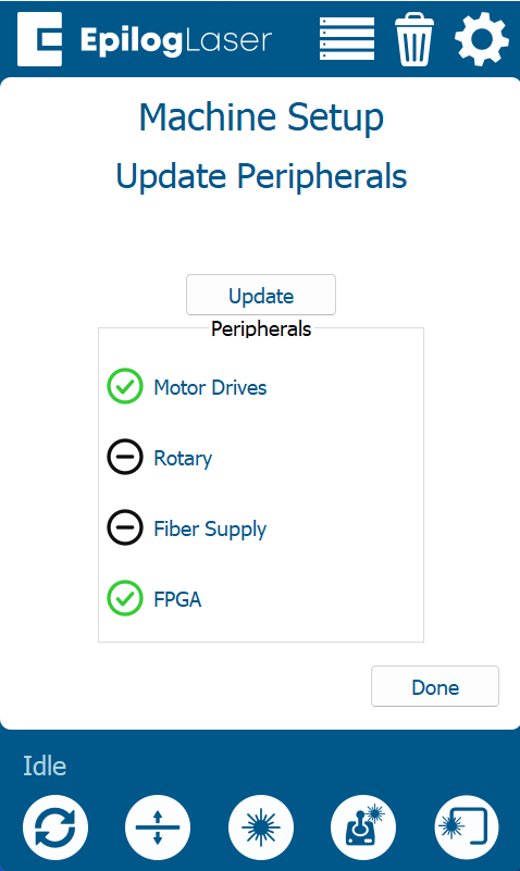
Once in the Peripheral Update menu, select all available components and press Update:
-
Allow the engraver to run the update process.
Warning: When running a peripheral update, do not power off the engraver. During a peripheral update, it is common for the display to power off. Once the update has been applied, the engraver will prompt to restart.
- Once the engraver prompts you to restart, power cycle the engraver.
Control Module Removal (Pro 24/36)
- Turn off the engraver.
- Disconnect power source.
- Open the top door of the engraver.
- Disconnect the connection cables.
- Remove the right panel.
- Attach the anti-static strap.
-
Loosen and remove the four (4) 5/32” Allen screws.
Note: The control module on the Fusion Pro 24 and Fusion Pro 36 interfaces with the engraver much differently than the Fusion Edge engraver. Whereas the Fusion Edge engraver houses electrical connections directly on the underside of the control module, the Fusion Pro 24 and Fusion Pro 36 engraver control module uses two (2) multi-pin connectors that interface with a backplane board. Take care when removing and installing the control module, ensuring that the multi-pin connectors are not damaged.
-
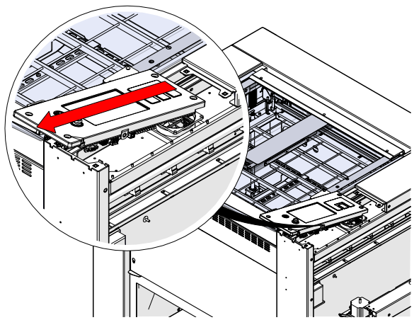
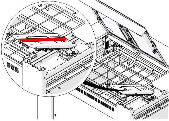
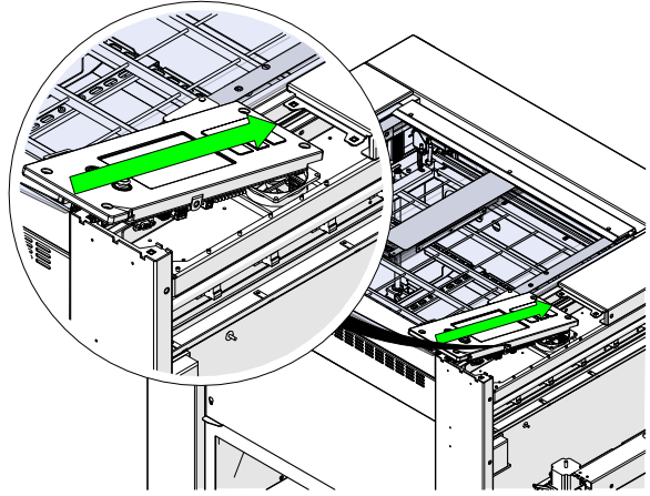
Gently raise the bottom of the control module to unseat the multi-pin connectors.
- Remove the control module.
Control Module Installation (Pro 24/36)
- Attach the anti-static strap.
-
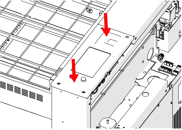
Position the control module aligning the screw holes.
-
Apply gentle pressure to seat the multi-pin connectors.
-
Ensure proper positioning before proceeding.
Note: If the control module does not seat with gentle pressure, do not force it down as the multi-pin connectors may become damaged. Lift the control module away from the engraver and ensure proper positioning with the chassis of the engraver before attempting installation again
-
Install and tighten the screws.
- Reconnect power and turn on the engraver.
Programming the Control Module
-
At the display panel, press the gear icon in the upper right-hand corner of the display to open the Settings menu:
-
Press Update:
-
Press Program Peripherals
-
Once in the Peripheral Update menu, select all available components and press Update:
-
Allow the engraver to run the update process.
Warning: When running a peripheral update, do not power off the engraver. During a peripheral update, it is common for the display to power off. Once the update has been applied, the engraver will prompt to restart.
- Once the engraver prompts you to restart, power cycle the engraver.