This document provides step-by-step instructions for the removal and installation of the backplane board for Fusion Pro 24 & 36 engravers. It includes all the necessary parts, tools, and materials required for the process, as well as detailed guidance on disconnecting electrical components, handling the board with care, and reassembling the engraver. Additionally, instructions for programming the new backplane board after installation are also covered to ensure proper system functionality. Please follow the outlined steps carefully to ensure a safe and successful replacement.
Backplane Board Removal
- Turn off the engraver.
- Disconnect the engraver from the power source.
- Disconnect the connection cable (USB, ethernet, fan control, etc.) from the engraver.
- Place the anti-static strap around your wrist and attach the clamp to a bare metal surface on the engraver.
- Remove the control module as outlined in the “Control Module Removal (Pro Only)” procedure.
-
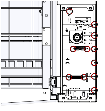
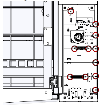
Once the control module is removed, loosen and remove the eleven (11) Phillips screws that secure the backplane board to the chassis of the engraver:
Note: If unable to access all of the screws in the previous step, the backplane rear cover can be removed.
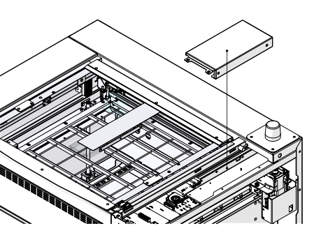
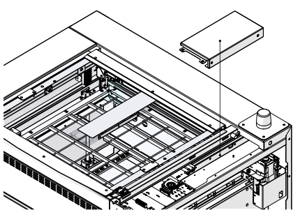
- Loosen and remove the two (2) Phillips screws that secure the rear backplane cover to the chassis of the engraver:

- Angle the backplane cover towards you and lift up to remove it:
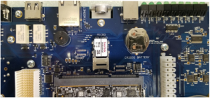
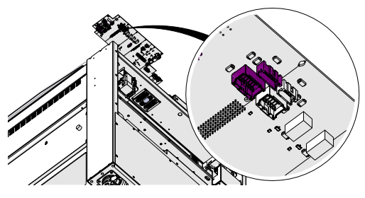
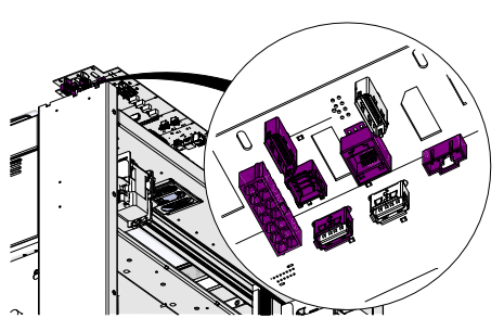
- Raise the bottom of the board upwards to gain access to the front electrical harnesses. Disconnect the eight (8) electrical harnesses from the underside of the backplane board:
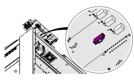
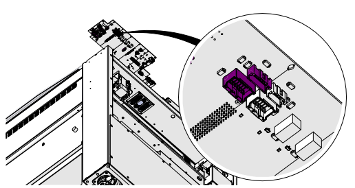
- Continue raising the bottom of the control module upwards to gain access to the flex cable. Disconnect the flex cable:
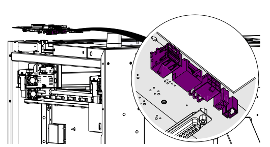
- Continue raising the bottom of the control module upwards to gain access to the rear electrical harnesses. Disconnect the seven (7) electrical harnesses from the underside of the backplane board:
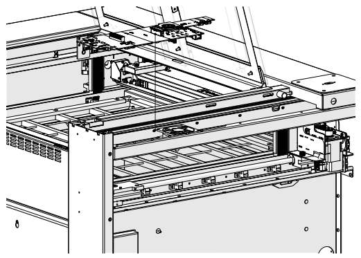
- Remove the backplane board:
Backplane Board Installation
- Place the anti-static strap around your wrist and attach the clamp to a bare metal surface on the engraver.
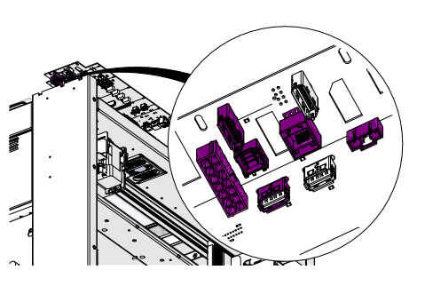
- Place the backplane board in position with the top of the board near the rear mounting location. While holding the board at an angle, connect the seven (7) electrical harnesses to the rear of the board:

-
Slightly lower the backplane board and connect the flex cable:

Note: The x-axis drive and fiber source receptacle both take a display port connector. Ensure that the display port cable is plugged in to the appropriate receptacle when reconnecting the front electrical harnesses.
- Continue lowering the backplane board and connect the eight (8) electrical harnesses to the front of the board:
- Install and tighten the eleven (11) Phillips screws that secure the backplane board to the chassis of the engraver:
- If the rear backplane cover was removed, place the cover in position. Install and tighten the two (2) Phillips screws that secure the cover to the chassis of the engraver:

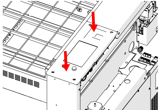
- Place the control module in position, ensuring that the screw holes in the display shroud align with the mounting screw holes on the chassis of the engraver:
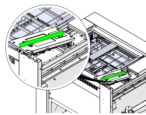
-
Once the control module is in the appropriate position, push down on the control module, applying gentle pressure to seat the multi-pin connectors:
Note: If the control module does not seat with gentle pressure, do not force it down as the multi-pin connectors may become damaged. Lift the control module away from the engraver and ensure proper positioning with the chassis of the engraver before attempting installation again.
- When the control module successfully seats, there will be tactile and audible feedback as the multi-pin connectors and receptacles join together.
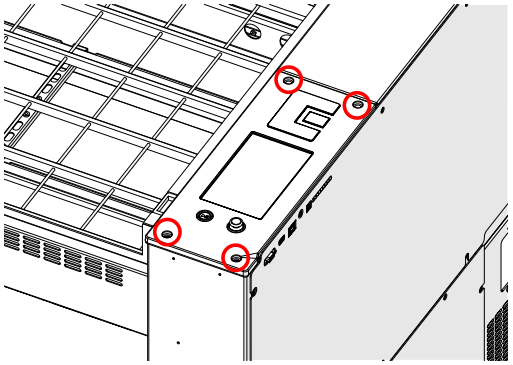
- Install and tighten the four (4) 5/32” Allen screws on the control module ensuring the two (2) longer screws are installed towards the rear:
- Reconnect to power and turn on the engraver.
Programming the Backplane Board
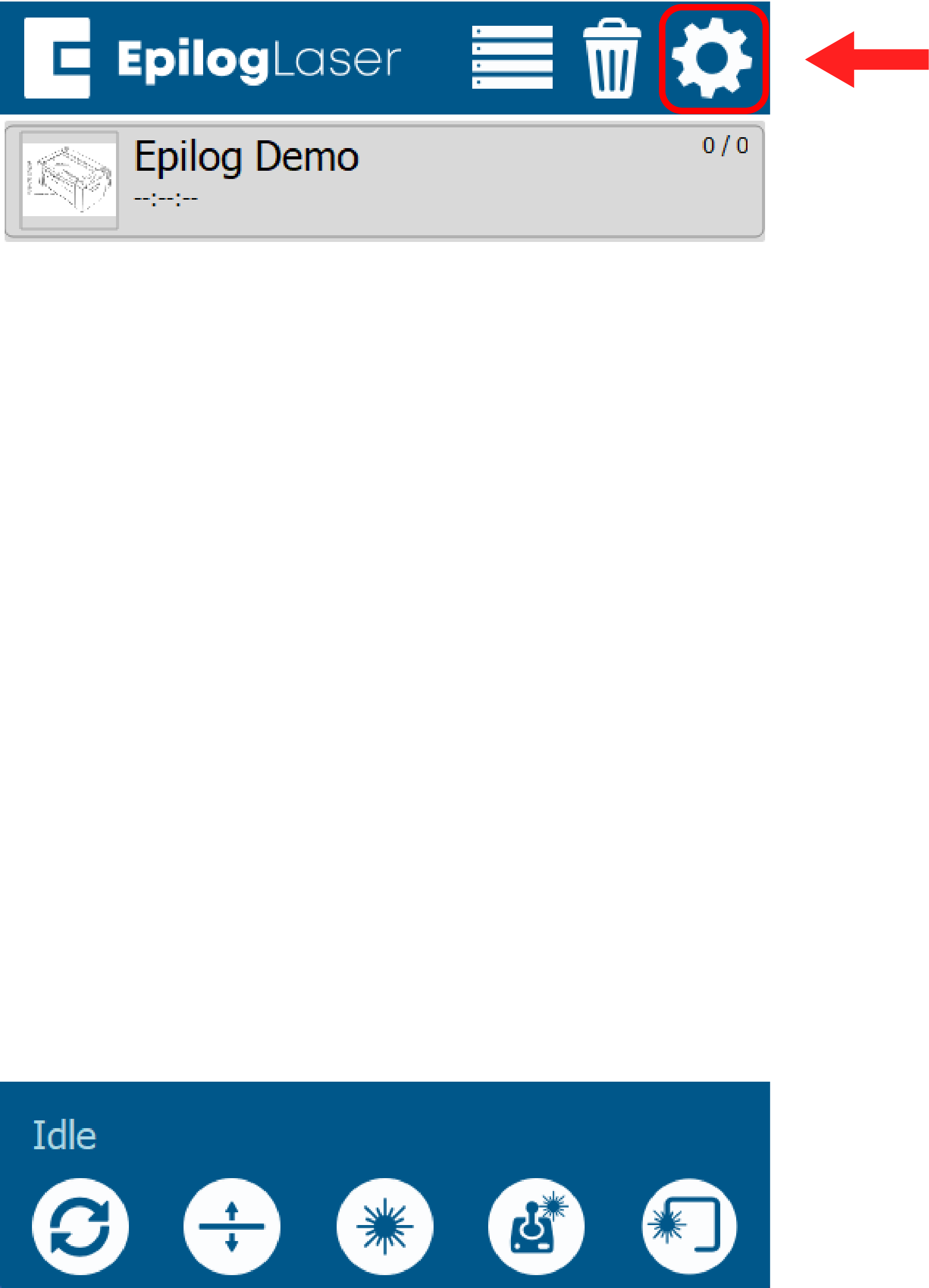
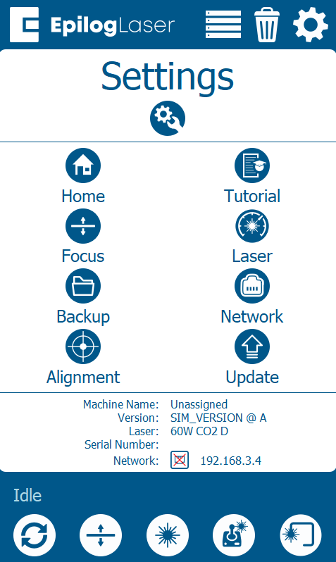
- At the display panel, press the gear icon in the upper right-hand corner of the display to open the Settings menu:
- Press Update:
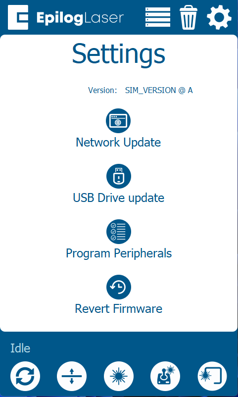
- Press Program Peripherals
- Once in the Peripheral Update menu, select all available components and press Update:
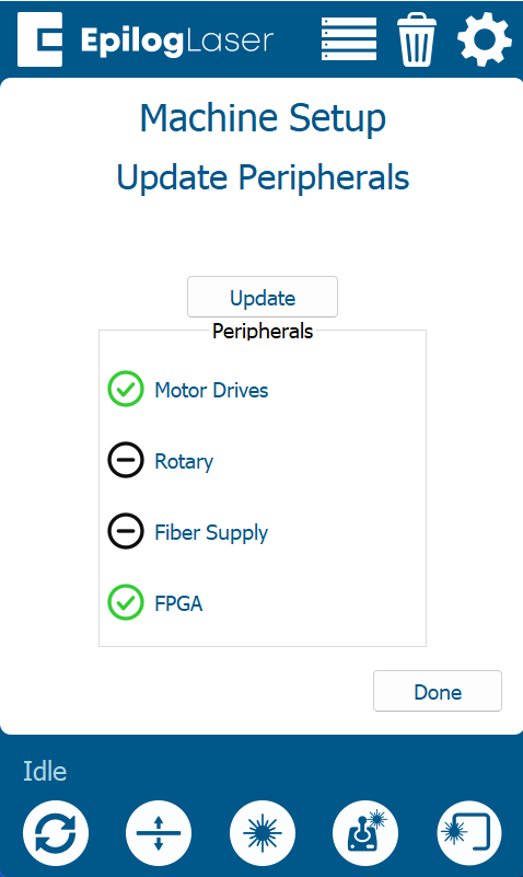
-
Allow the engraver to run the update process.
Warning: When running a peripheral update, do not power off the engraver. During a peripheral update, it is common for the display to power off. Once the update has been applied, the engraver will prompt to restart.
- Once the engraver prompts you to restart, power cycle the engraver.