Applies to: Fusion Pro 32 • Fusion Pro 48
This guide provides step-by-step instructions for upgrading the floating backplane board in Fusion Pro 32 and 48 engravers. Designed for models manufactured before mid-2020, this procedure ensures proper installation and configuration of the new backplane board. By following these instructions, you can safely remove the old backplane, install the updated components, and program the system for optimal performance.
Backplane Board Removal
-
Turn off the engraver:
Power down the system completely before starting the procedure.
-
Disconnect power:
Unplug the engraver from the power source to ensure safety.
-
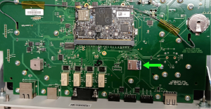
Remove all connection cables:
Disconnect USB, Ethernet, fan control, and any other attached cables from the rear of the engraver.
-
Attach anti-static protection:
Place the anti-static strap around your wrist and clip it to a bare metal surface.
-
Loosen the control module screws:
Remove the two Phillips screws securing the control module to the chassis.
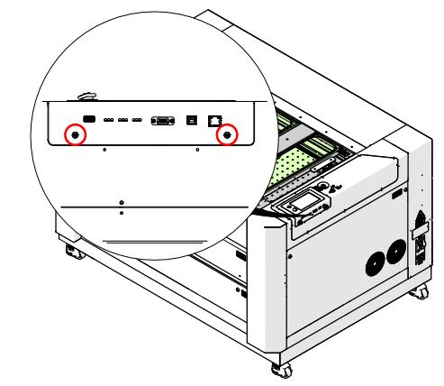
Figure 1: Loosening the Phillips screws on the control module. -
Remove the control module:
Grip the screws and gently pull the control module straight away from the engraver.
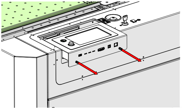
Figure 2: Pulling the control module straight away from the engraver. -
Remove the upper right corner panel:
Loosen and remove the nine (9) T8 Torx screws securing the panel.
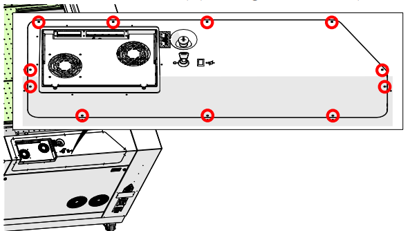
Figure 3: Removing the Torx screws securing the upper right corner panel. -
Disconnect panel harnesses:
Gently lift the panel and disconnect the key switch and emergency stop electrical connections.
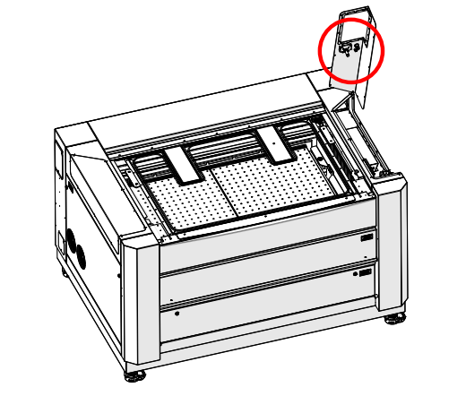
Figure 4: Disconnecting the key switch and emergency stop connections. -
Remove the fan tray:
Loosen and remove the five Phillips head screws securing the fan tray to the cabinet. Carefully lift and remove the tray from the engraver.
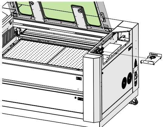
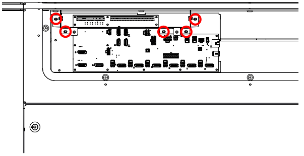
Figure 5: Removing the fan tray from the engraver cabinet. -
Disconnect backplane harnesses:
Unplug all electrical harnesses connected to the backplane board. Taking a photo for reference is highly recommended.

Figure 6: Disconnecting the electrical harnesses from the backplane board. Note: Each receptacle and harness on the backplane board is labeled. A photo reference can help ensure proper reconnection later.
-
Remove the backplane screws:
Loosen and remove the sixteen (16) Phillips screws securing the backplane board.
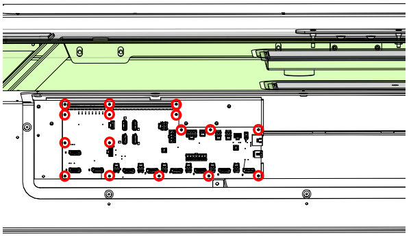
Figure 7: Removing the screws securing the backplane board. -
Remove the backplane board:
Carefully lift the backplane board away from the engraver and set it aside on an anti-static surface.
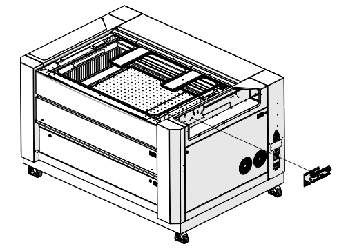
Figure 8: Removing the backplane board from the engraver assembly.
Backplane Board Installation
-
Remove the mounting plate:
Inside the engraver cabinet, remove the three Allen screws securing the backplane mounting plate.
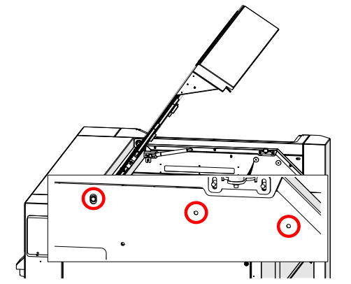
Figure 9: Removing the Allen screws securing the mounting plate. -
Position the new hardware:
Align the new backplane board mounting bracket, spacers, and mounting plate in place.
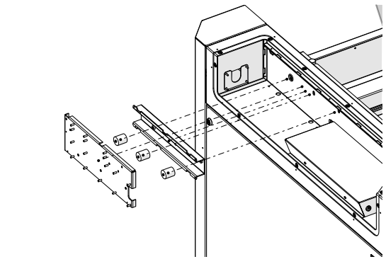
Figure 10: Positioning the new backplane mounting components. -
Secure the mounting plate:
Install the three Phillips head screws from inside the engraver cabinet.
Figure 11: Securing the mounting plate with Phillips screws. -
Attach anti-static protection:
Place the anti-static strap around your wrist and clip it to a bare metal surface.
-
Install the new backplane board:
Position the board on the mounting posts and secure it with sixteen Phillips screws.
Figure 12: Installing and securing the backplane board. -
Reconnect all harnesses:
Plug in all labeled electrical harnesses to the corresponding connectors on the backplane board.
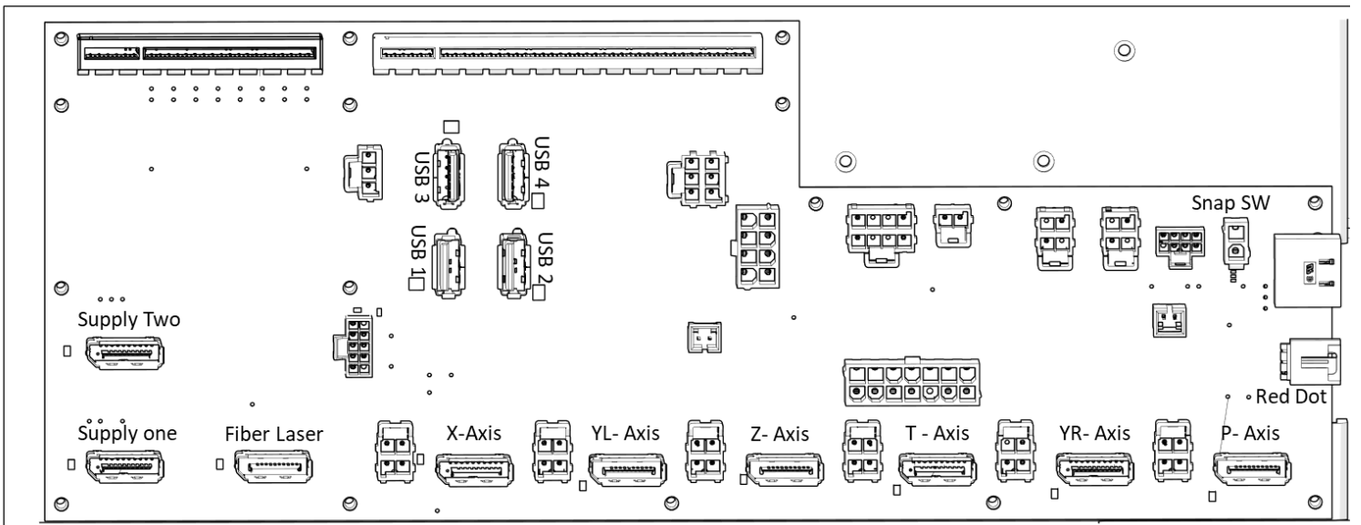
Figure 13: Reconnecting all electrical harnesses on the backplane board. -
Install the fan tray:
Reposition the fan tray and secure it with five Phillips head screws.
Figure 14: Installing and securing the fan tray. -
Reinstall the corner panel:
Reconnect the key switch and emergency stop harnesses, then position the panel back in place.
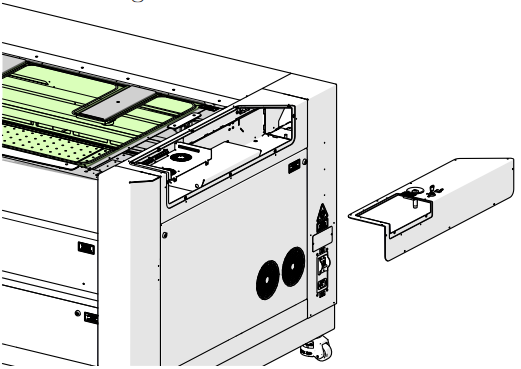
Figure 15: Reconnecting panel harnesses and reinstalling the corner panel. -
Secure the corner panel:
Tighten the nine T8 Torx screws to fasten the panel securely.
Figure 16: Securing the corner panel with T8 Torx screws. -
Reinstall the control module:
Slide the control module back into the housing and tighten the two Phillips screws.
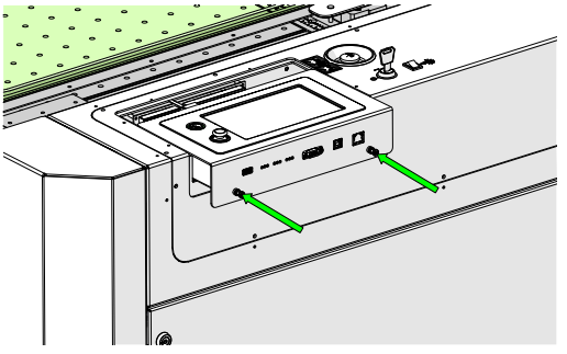
Figure 17: Reinstalling and securing the control module. -
Reconnect power:
Plug in the power cable and turn on the engraver to confirm operation.