
This procedure outlines how to replace both the Carriage Camera PCB and the X-Axis USB-C cable on a 16000 Series Fusion Pro laser system. The Carriage Camera PCB also integrates the Auto Focus sensor, which is critical to system performance. Follow each step carefully to ensure proper installation and avoid damage to internal components. Camera recalibration will be required after replacing the PCB.
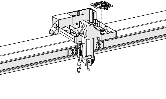
Carriage Camera PCB Replacement
-
Power the engraver OFF.
-
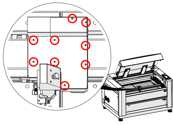
Remove nine (9) T7 Torx screws on carriage cover.
-
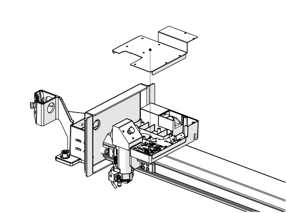
Remove the carriage cover.
-
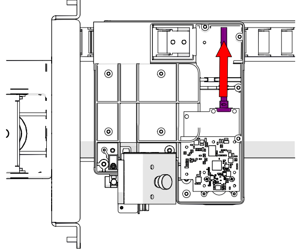
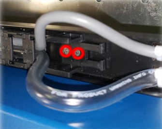
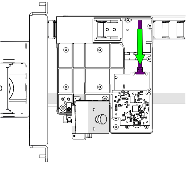
Disconnect the grey USB-C cable from the carriage camera PCB.
-
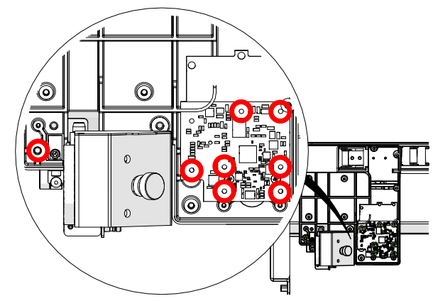
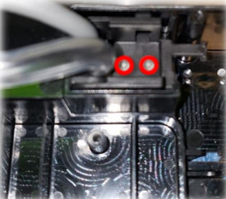
Remove eight (8) T4 Torx screws that secure the carriage camera PCB.
-
Carefully remove the circuit board.
Note: After replacing the carriage camera PCB, you will need to recalibrate your cameras. Please follow this link for more information on how to complete the Camera Calibration.
USB-C Cable Replacement
-
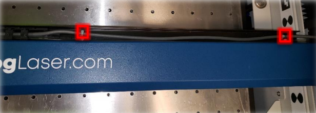
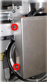
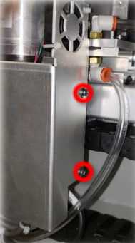
Remove two (2) T8 Torx screws on each end of the cable chain.
-
Cut the two (2) plastic cable ties shown below.
-
Pull the USB-C cable through the cable chain.
-
Using a 5/32″ hex wrench, remove the right-side panel of the machine.
-
Loosen the four (4) phillips head screws and remove the X-Axis Drive PCB cover.
-
Cut the final cable tie.
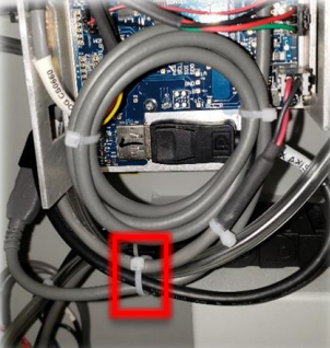
-
Pull the USB-C cable out through the right side of the machine.
-
Unplug the USB-C cable from the extension cable to the left of the motor.
-
Feed the replacement cable back through the machine and cable chain.
-
Plug the USB-C cable into the carriage camera PCB.
-
Reattach the cable chain with the two (2) T8 Torx screws.
-
Plug the USB-C cable into the extension port by the motor.
-
Use replacement cable ties to attach the USB-C cable to the X-Axis rail.
-
Replace all covers.
