Estimated time: 30–45 minutes • Skill: Intermediate
This guide explains how to remove and reinstall the X-Axis assembly on the Epilog FiberMark laser engraver. Removing the X-Axis rail is necessary for tasks such as replacing the X-Axis belt or servicing the bearing guard on the underside of the rail.
You’ll need a #2 Phillips screwdriver and a replacement nylon tie for the ribbon cable. The procedure follows four high-level steps: remove the rail, replace the belt (if applicable), reinstall the rail, and check optical alignment.
Procedure
-
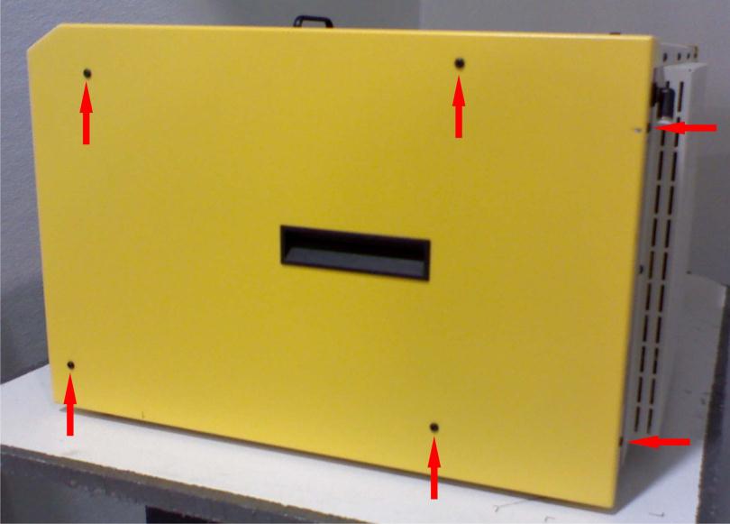
Power down and remove side panels.
Turn off the machine and disconnect it from the power source. Remove the left and right side panels by removing the six Phillips head screws on each side (four on the side and two on the rear) as shown in Picture 1.
-
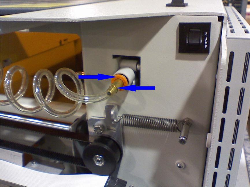
Disconnect the air assist line.
Remove the air assist connection from the X-Axis assembly by pushing in on the ring around the connector and pulling the connector free. This can require firm force in both directions. See Picture 2.
-
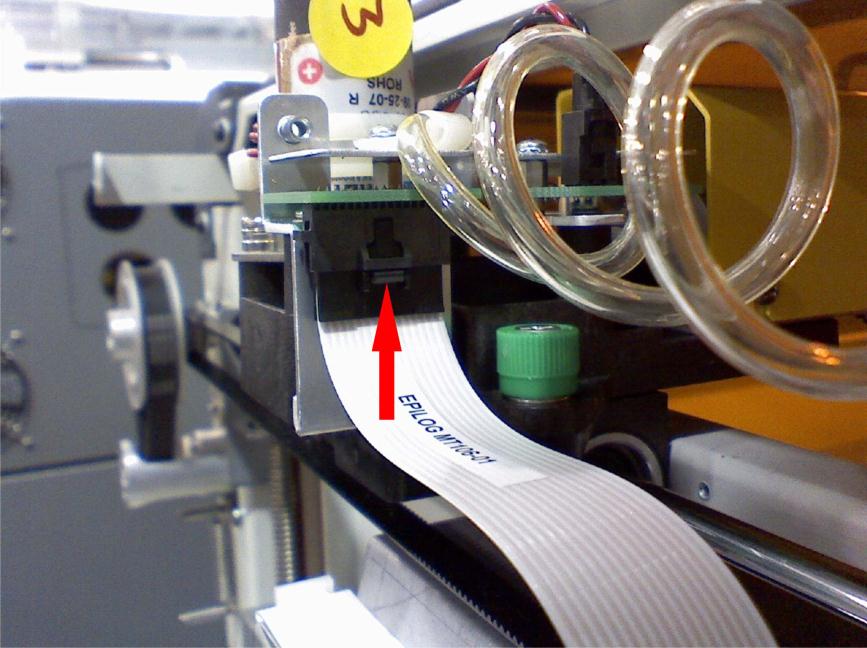
Unplug the white ribbon cable.
On the right-hand side of the rail assembly there is a circuit board with a white ribbon cable. Depress the thumb clip on the connector and pull the connector down to unplug it (Picture 3).
-
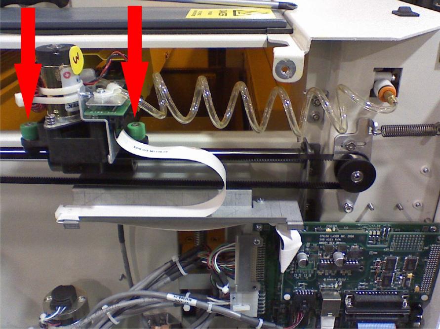
Loosen the green-cased screws near the rail.
Using a #2 Phillips screwdriver, loosen the two screws with green casings on the X-Axis assembly — one just right/rear of the ribbon connector and the other on the front next to the X motor (Picture 4).
-
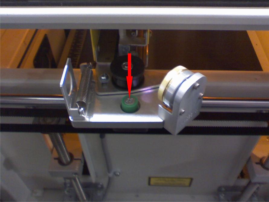
Loosen the left-side green-cased screw.
Loosen the green-cased screw on the left side of the X-Axis assembly with the Phillips screwdriver (Picture 5).
-
Remove the X-Axis assembly.
Lift up both sides of the X-Axis assembly to free it from the brackets. Position the right side to the rear and bring the left side forward. Slide the assembly to the right until the left side clears the chassis wall, then lift the left side so the X motor on the right clears the chassis. Carefully remove the X-Axis assembly from the machine.
-
Reinstall the X-Axis assembly.
To reinstall, reverse steps 5 back down to 1. Replace the ribbon cable tie with a new nylon tie when securing the white ribbon cable to the X-Axis assembly. After reinstalling, perform the alignment checks described in the Mini alignment tech note.
-
Final checks and support.
Once reinstalled and aligned, reconnect power and test motion. If you have further questions contact Epilog technical support.