
X-Axis Assembly Replacement

Replace the gantry that runs across the x-axis of your machine.

Introduction

In this lesson we’ll walk through replacing the Epilog Mini/Helix X-Motor.

Remove Side Panels

Shut off the laser and remove the power cord from the machine.

Flipping the machine's power switch.

Remove the left side panel by loosening the four screws on its main face, as well as the two screws on the back.

Removing the screws on the left panel's main face.Removing the screws on the left panel's back face.

Pulling the left panel off of the chassis.

Remove the right side panel by loosening the four screws on its main face, as well as the two screws on the back.

Removing the screws on the right panel's main face.Removing the screws on the right panel's back face.

Pulling the right panel off of the chassis.

Remove X-Axis Assembly

Disconnect the Air Assist Coil by pushing in the orange ring and then pulling the air hose out.

Grasping the Air Assist Coil.

Cut the white zip tie around the white ribbon cable.

Scissors cutting the zip tie around the white ribbon cable.

Disconnect the Y-Axis flex cable.

Pulling out the Y-Axis flex cable.

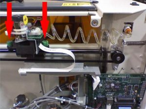
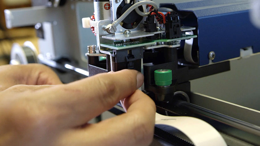
Unscrew the two green captive screws on the right side of the X-Axis Assembly.

Unscrewing the front captive screw on the right side of the X-Axis Assembly.Unscrewing the back captive screw on the right side of the X-Axis Assembly.

Unscrew the green captive screw on the left side of the X-Axis Assembly.

Unscrewing the green captive screw on the left side of the X-Axis Assembly.

Open the lid of the machine.

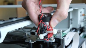
To remove the X-Axis Assembly, lift it carefully, especially when lifting the right side of the Assembly. Bring the right side forward a little to ensure the motor clears the frame rail.

Pulling the X-Axis Assembly out the right side of the machine.

Reinstall X-Axis Assembly

Install the X-Axis assembly by placing the Assembly on the brackets, making sure to line up the Assembly onto the pins.

Putting the X-Axis Assembly back in through the right side of the machine.Placing the X-Axis Assembly on its mounting pins.

Tighten the green captive screws on both sides of the X-Axis Assembly.

Tightening the green captive screw on the left side of the machine.Tightening the green captive screws on the right side of the machine.

Move the X-Axis Assembly to the front and back to make sure the Y-axis moves smoothly.

Pushing the X-Axis Assembly to the back of the machine.

Reconnect the Y-Axis flex cable and secure it with a Zip Tie.

Plugging in the Y-Axis flex cable.

Reconnect the Air Assist Coil.

The Air Assist Coil plugged into the machine.

Reinstall Side Panels

Replace the right side panel, inserting the four screws on the panel’s main face, as well as the two screws on the back.

Putting on the right side panel.

Inserting the screws on the main face of the right side panel.Inserting the screws on the back of the right side panel.

Replace the left side panel, inserting the four screws on the panel’s main face, as well as the two screws on the back.

Putting on the right side panel.

Inserting the screws on the main face of the left side panel.Inserting the screws on the back of the left side panel.

Plug the machine in and turn it on.

Plugging the power cord into the machine.

  • ID:
    TA-112
  • Date:
    09/24/2024

Tools:

  • #1 Philips Screwdriver
  • Scissors

Parts & Resources:

  • Zip Tie