In this lesson we’ll walk through replacing the Epilog Mini/Helix X-Motor.
Remove Side Panels
Shut off the laser and remove the power cord from the machine.

Remove the left side panel by loosening the four screws on its main face, as well as the two screws on the back.


Remove the right side panel by loosening the four screws on its main face, as well as the two screws on the back.


Loosen X-Axis Belt
Remove the cover on the X-Axis Assembly by loosening the screws on the front and rear of the beam and pulling the cover up. Do not remove these screws completely.


Loosen the X-axis belt as follows:
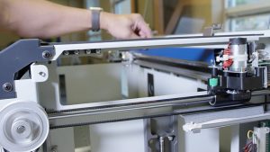
On the left side of the X-Axis Assembly, locate the idler pulley that the belt wraps around. It is mounted to a sliding plate which has one screw and a spring attached.
Loosen the Philips screw that holds the sliding plate in place.

While holding the sliding plate to the right hand side of the engraver, tighten the screw. This will hold the pulley in place and keep tension off of the X-axis belt.

Remove Old X-Motor
Identify the Motor Assembly on the right side of the X-Axis Assembly. Locate the motor wires and remove them by squeezing the quick-disconnect plugs between your thumb and forefinger to release the connectors from their sockets.


Remove the Air Assist Coil.

Unscrew and remove the fan assembly.


Identify and unscrew the captive screws which mount the motor to the X-Axis Assembly.


Remove the motor by pulling it straight up. You may need to angle the motor slightly so that the belt falls from the drive pulley.

Install New X-Motor
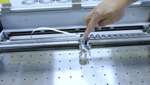
Install the new X-Motor. With your index finger, pull the belt and loop the belt around the silver pulley. Place the motor so that the captive screws are aligned with the mounting posts.

Tighten the captive screws to hold the motor in place.


Replace and fasten the fan assembly over the circuit board.

Connect the motor and fan wires by plugging the black connectors into the circuit board.


Reconnect the Air Assist Coil.

On the left side of the X-Axis Assembly, locate the pulley which the belt wraps around. Loosen the Philips screw holding the sliding plate in place. The spring will pull the belt tight.

Retighten the Philips screw to keep the belt tight as the engraver operates.

Check that the belt is on the center of both pulleys on the left and right sides of the assembly.
Replace the cover on the X-Axis Assembly and tighten the screws on the front and rear of the beam.


Reinstall Side Panels
Replace the right side panel, inserting the four screws on the panel’s main face, as well as the two screws on the back.


Replace the left side panel, inserting the four screws on the panel’s main face, as well as the two screws on the back.


Plug the machine in and turn it on.