
This guide provides step-by-step instructions for safely removing and replacing the laser tube in the Epilog Zing 24 laser system. The process includes disassembly of key components, careful disconnection of power and data cables, and reinstallation procedures to ensure proper alignment and secure mounting of the new laser tube. Please follow each step closely and refer to the included images for clarification.
Laser Removal:
- Lower the table to the bottom of the machine.
- Turn off the machine.
- Disconnect the machine from its power source.
-
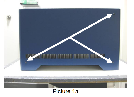
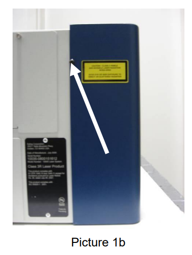
Remove the four Phillips screws which secure the left-hand side panel. There are three on the side and one on the rear as shown in picture 1a and 1b.
-
Remove the side panel.
-
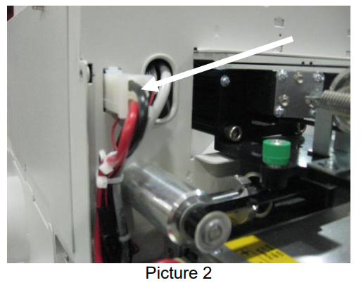
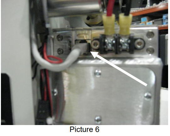
Disconnect the laser power connection, shown in picture 2, from the machine’s chassis. The connection is located above and behind the laser assembly. There is a lock on the connection—depress the lock and pull the connection toward you.
-
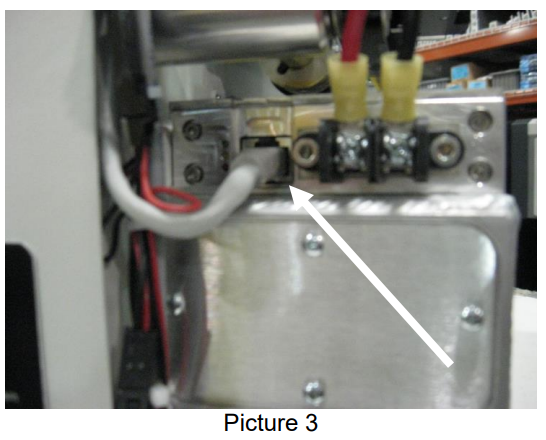
Disconnect the data cable from the laser assembly. The data cable is shown in picture 3. This connection works the same as your network cable. There is a lock on the connection that must be depressed before the connector will come out of the laser tube.
-
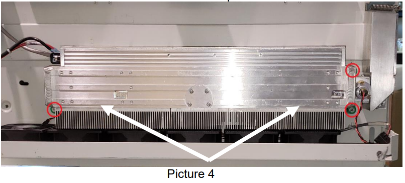
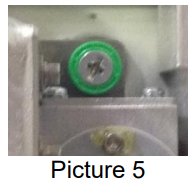
The laser is held in place by three green mounting screws. The mounting screws are located on the laser tube itself. The location of the mounting screws is shown in picture 4.
-
The 3 mounting screws are captive screws. You will only need to loosen them to remove the laser tube.
-
Once the laser mounting screws are loosened, you will note that the Laser guide pin fits into a slot in your engraver’s chassis. To remove the laser assembly, lift it slightly and move the laser assembly so that the Laser Guide pin head is lined up with the hole in the machine’s chassis. The laser can now be removed from the machine.
Laser Installation:
-
Align the laser’s guide pins with the holes in the side of the machine’s chassis and push the laser assembly against the side of the machine. Then slide the laser assembly toward the front of the machine.
-
Loosely install the three screws in each of the laser mounting plates. Once all three screws have been loosely installed, tighten all of the mounting screws.
-
Reconnect the data cable to the laser assembly, as shown in picture 6.
-
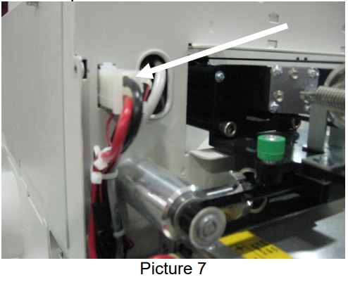
Reconnect the laser’s power harness to the chassis as shown in picture 7.
-
Follow the Zing Laser Alignment instructions after completing the installation procedure.
