Replacing the Y-axis belt on your Epilog Zing laser machine is a straightforward process that ensures optimal performance and precision for your engraving and cutting projects. Whether you’re working with a Zing 16 or Zing 24 model, this step-by-step guide will walk you through the necessary tools and procedures to successfully remove and install a new Y-axis belt. With detailed instructions and accompanying visuals, you’ll be able to complete this maintenance task efficiently and get your machine back to peak operation in no time.
Procedure
-
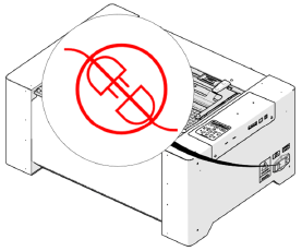
Disconnect power.
-
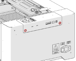
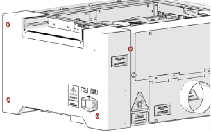
Loosen two (2) captive screws.
-
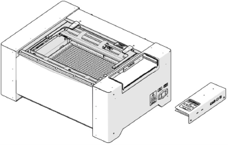
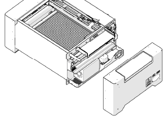
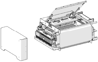
Remove control board.
-
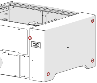
Remove four (4) Phillips head screws.
-
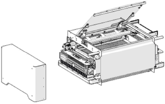
Remove side panel.
-
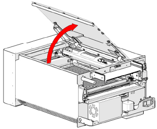
Open top door.
-
Remove four (4) Phillips head screws.
-
Remove side panel.
-
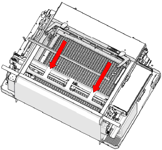
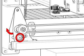
Move X-Axis rail to front of machine.
-
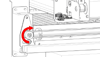
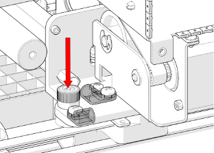
Loosen green captive screw.
-
Move X-Axis rail to back of machine.
-
Loosen green captive screw.
-
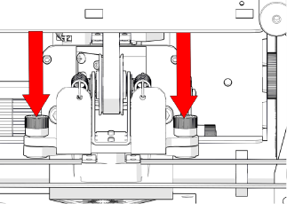
Loosen two (2) green captive screws on left-side of X-Axis rail.
-
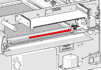
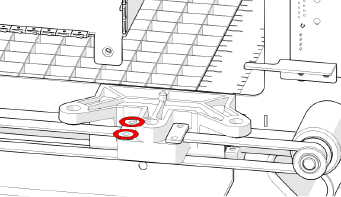
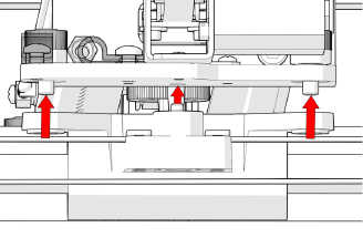
Move X-Axis to front of machine and lift.
-
Move bearing block to rear of machine.
-
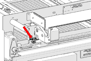
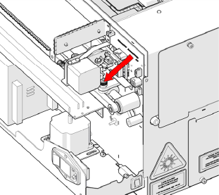
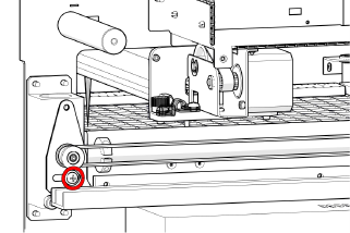
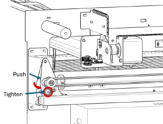
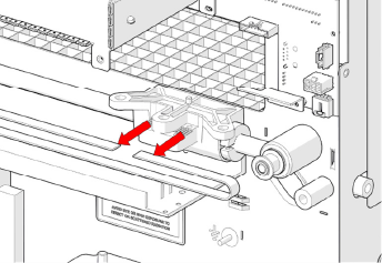
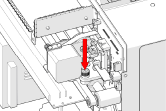
Loosen tensioner screw.
-
Push and hold tensioner pulley towards rear, then tighten screw.
-
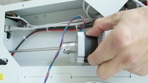
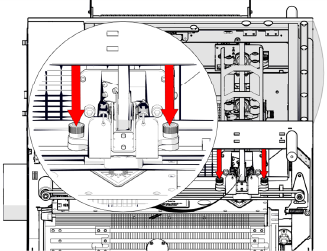
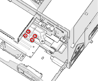
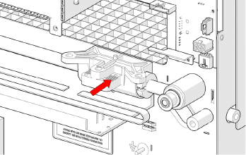
Remove four (4) Phillips head screws on belt clamps.
-
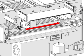
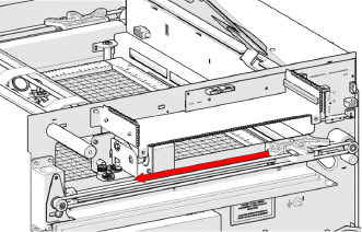
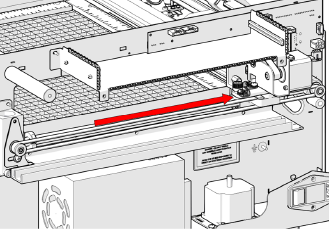
Remove belt.
-
Install replacement belt.
-
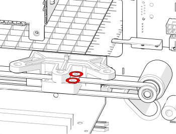
Install two (2) Phillips head screws on rear belt clamp.
-
Feed belt around pulley with teeth facing pulley.
-
Feed belt around front pulley.
-
Install two (2) Phillips head screws on front belt clamp.
-
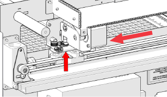
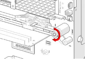
Tension belt by unscrewing and tightening.
Note: If replacing both sides, repeat steps 16 – 25 for left-side.
-
Move bearing block towards front of machine.
-
Align X-Axis rail and bearing block.
-
Tighten green captive screws on left-side of X-Axis rail.
-
Tighten green captive screw.
-
Move X-Axis rail to rear of machine.
-
Tighten green captive screw.
-
Install left-side panel.
-
Install four (4) Phillips head screws.
-
Install right-side panel.
-
Install four (4) Phillips head screws.
-
Insert control board.
-
Tighten two (2) captive screws.
-
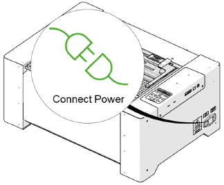
Connect power.