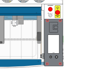
Veiligheid gaat voor alles: Zorg ervoor dat het lasersysteem volledig is uitgeschakeld en dat de stekker uit het stopcontact is gehaald voordat je interne elektronische onderdelen aanraakt of loskoppelt. Raak geen blootliggende onderdelen van de voeding aan.
Belangrijk: De besturingskaart, de backplane en andere elektronische onderdelen zijn gevoelig voor elektrostatische ontlading (ESD). Draag altijd een antistatische polsband die is geaard op het blanke metalen chassis van de machine voordat je deze onderdelen aanraakt, om schade te voorkomen.
Deel 1: De besturingskaart verwijderen
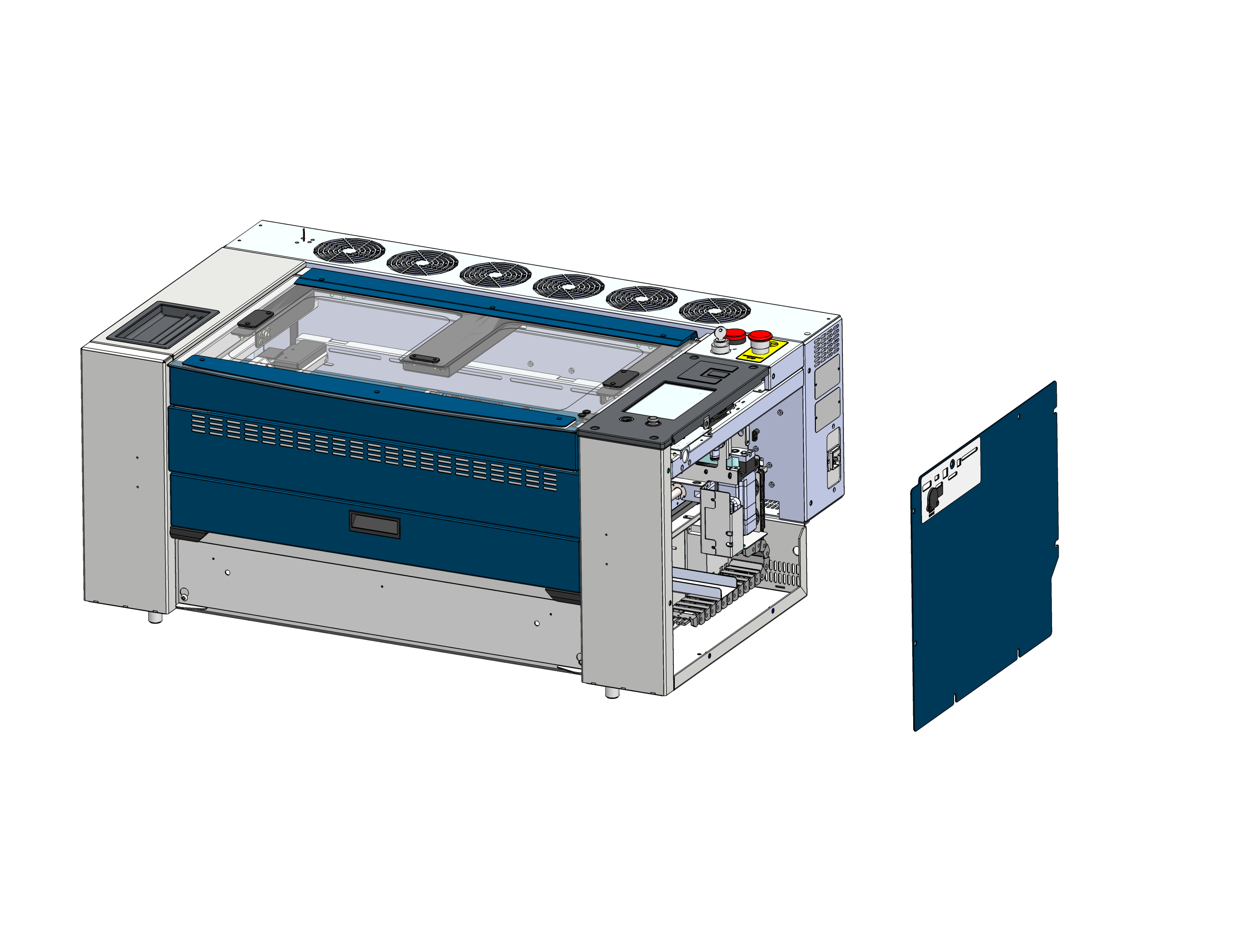
Verwijder zijpaneel
Zoek het rechterzijpaneel van het laserchassis en haal het eraf om bij de elektronica te kunnen komen.
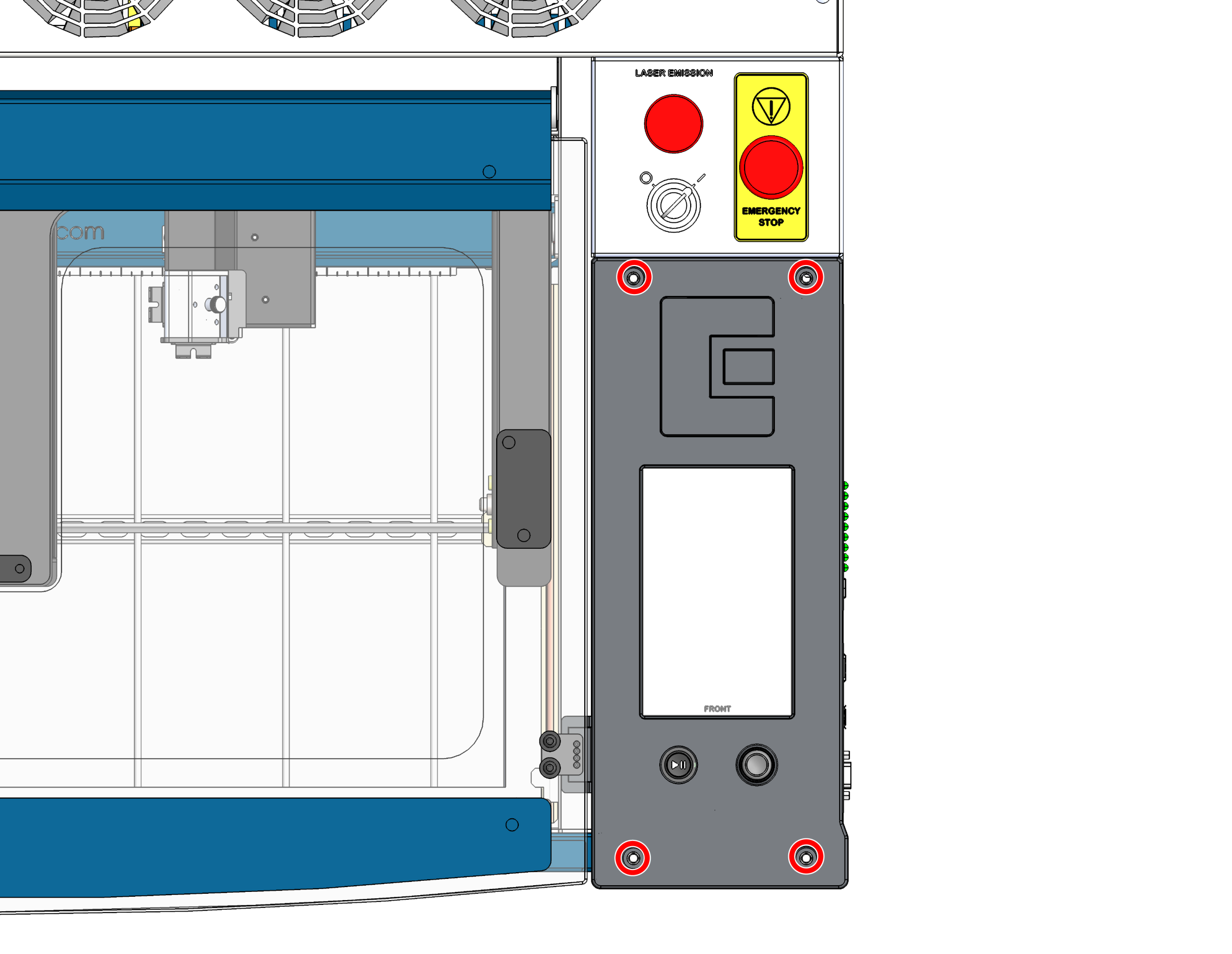
Draai de schroeven van de besturingskaart los
Draai de 4 schroeven los waarmee de besturingskaart aan het chassis vastzit.
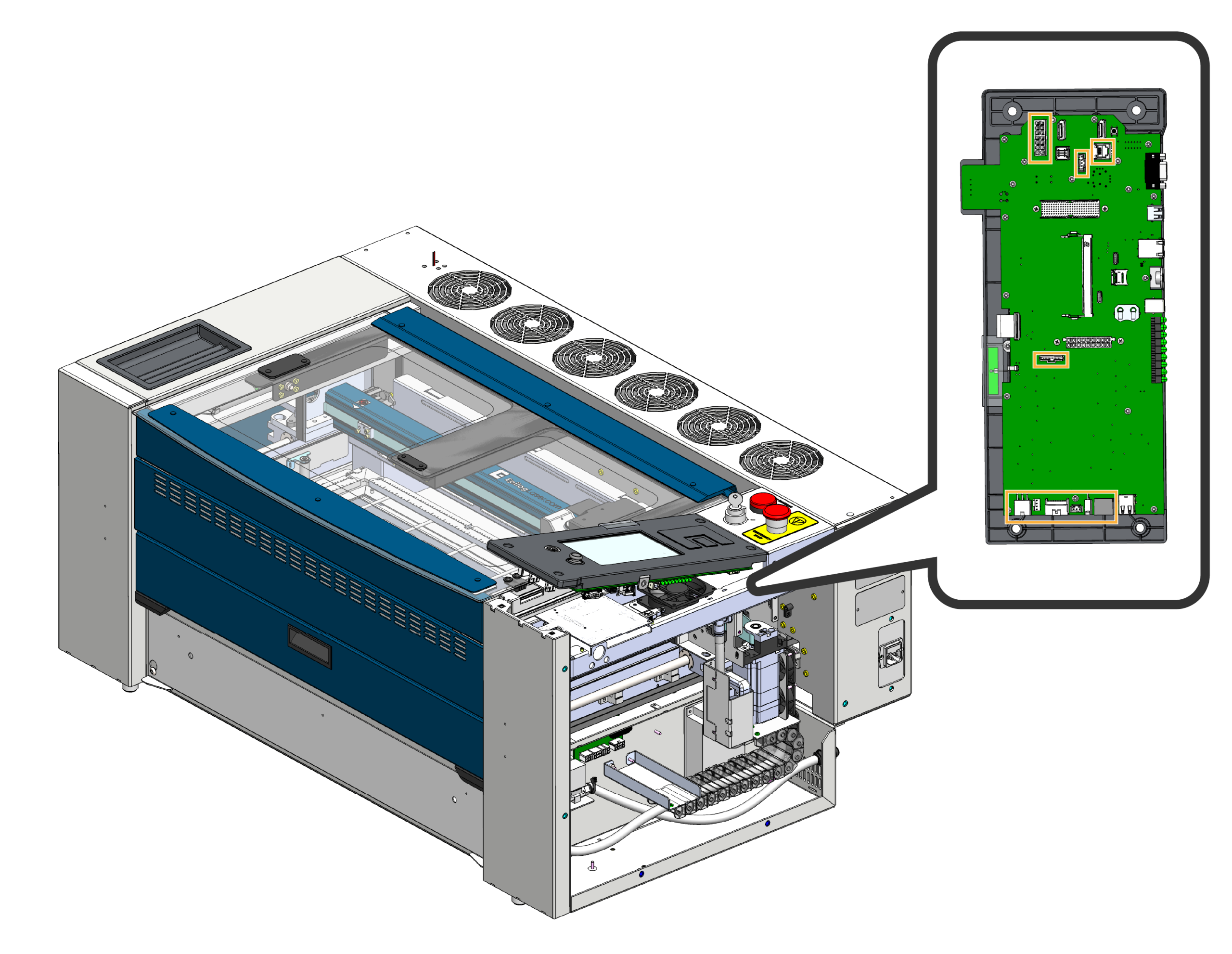
De kabelboom loskoppelen
Kantel de voorkant van de besturingskaart voorzichtig omhoog en koppel de kabelbomen los die op de besturingskaart zijn aangesloten.
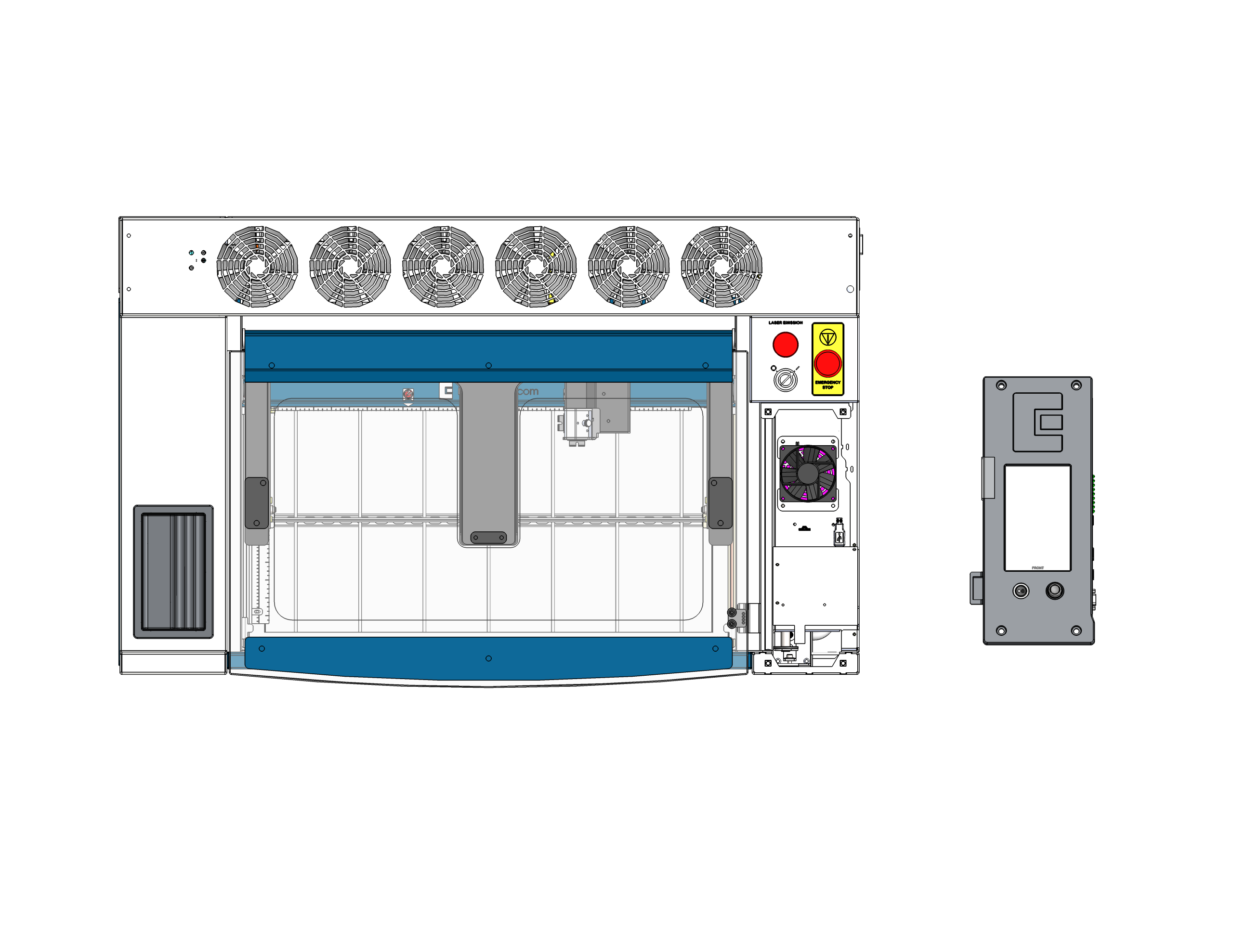
Verwijder de besturingskaart
Haal de besturingskaart uit de machine en haal hem er helemaal uit. Leg hem met de voorkant naar beneden op een veilig, statischvrij oppervlak. Belangrijk: Zorg ervoor dat de joystick ofwel over de rand van het oppervlak hangt, ofwel op een zacht materiaal ligt, zodat hij niet wordt platgedrukt of beschadigd terwijl je aan de achterkant van de kaart werkt.
Deel 2: SD-kaart en knoopcelbatterij vervangen
Nu de printplaat veilig met de bedrukte kant naar beneden ligt, kun je de SD-kaart en de knoopcelbatterij op de printplaat makkelijk bereiken en vervangen.
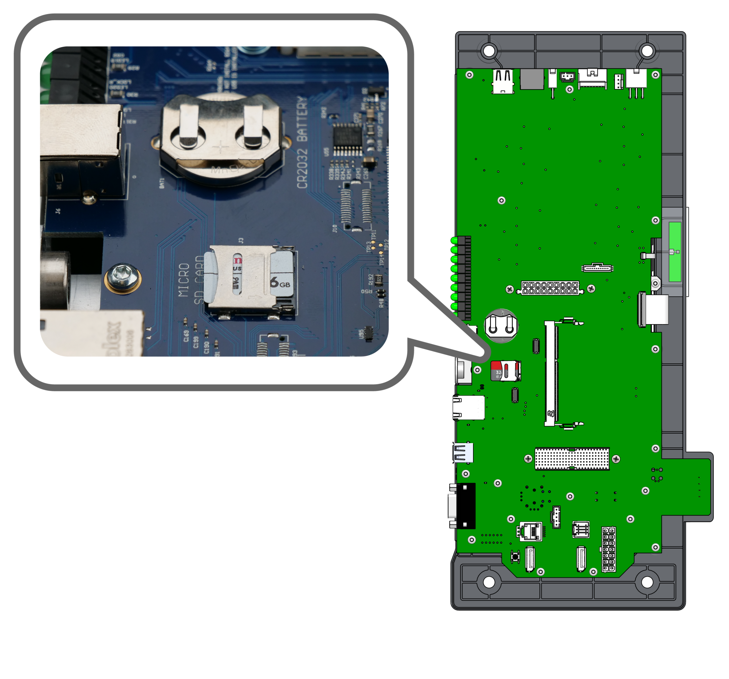
Componenten zoeken
Zoek de micro-SD-kaart en het compartiment voor de CR2032-knoopcelbatterij aan de achterkant van de besturingskaart.
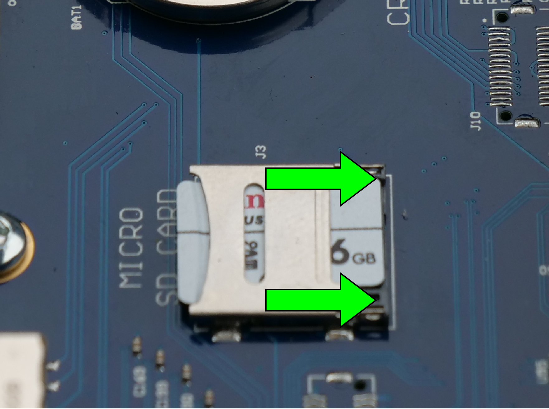
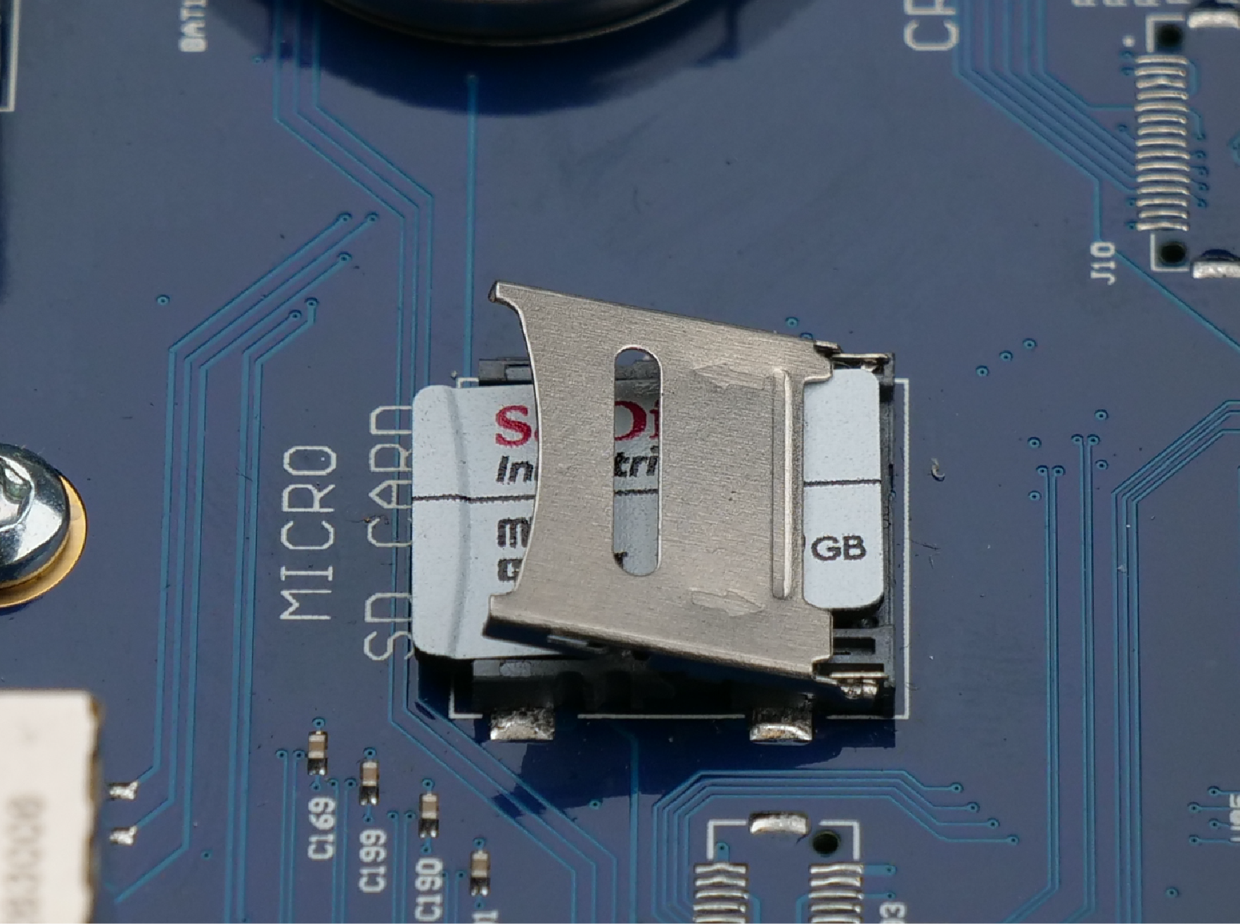
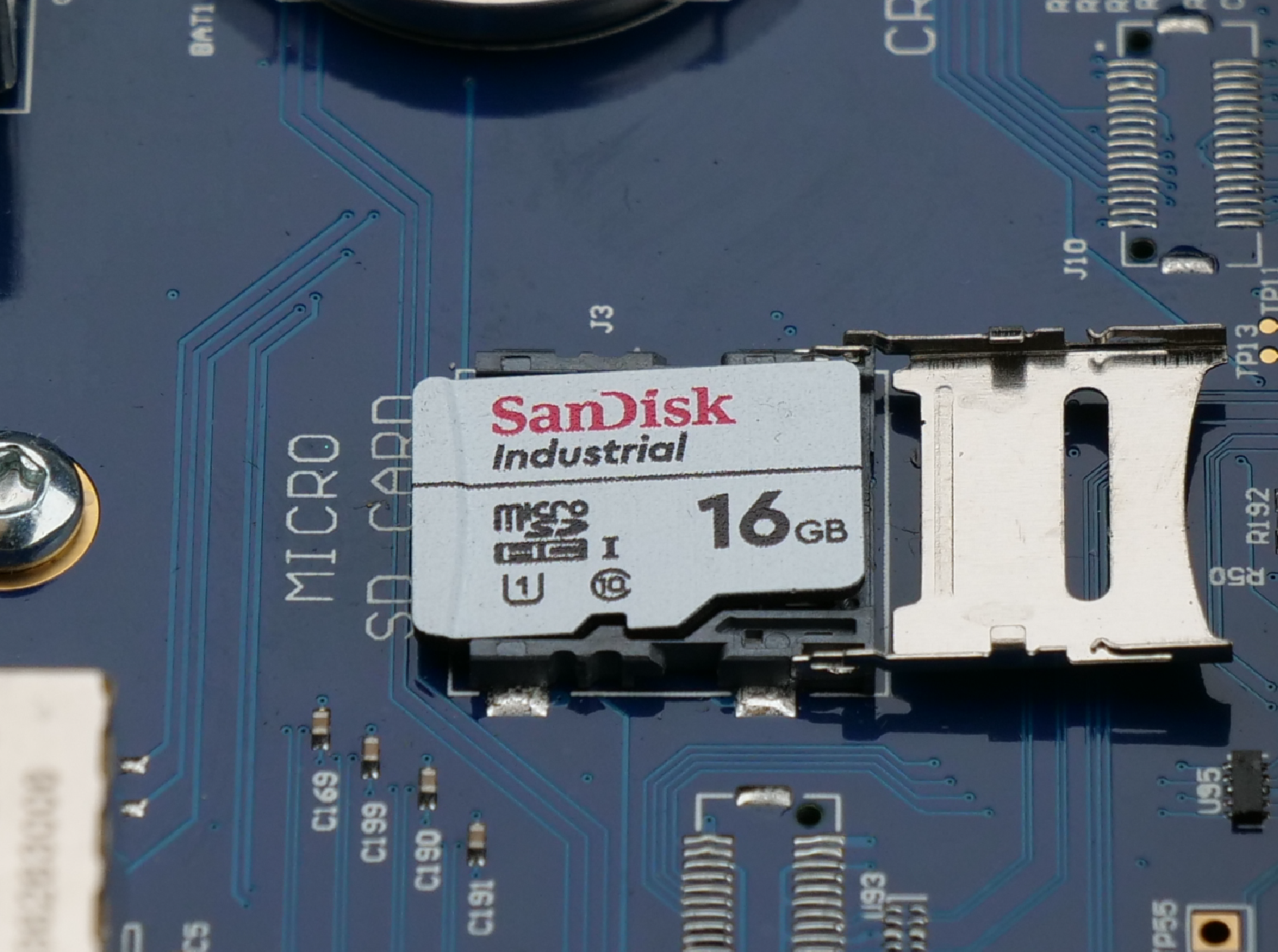
SD-kaart vervangen
Klik door de afbeeldingstabbladen om de stappen voor het vervangen te bekijken:
- Ontgrendelen: Schuif de metalen vergrendeling naar binnen (in de richting van de pijl) om hem te ontgrendelen.
- Openen: Til de ontgrendelde metalen klem omhoog om de SD-kaart bloot te leggen.
- Vervangen: Haal de oude SD-kaart eruit, plaats de nieuwe erin, sluit het klepje en schuif de vergrendeling weer naar buiten om hem vast te zetten.
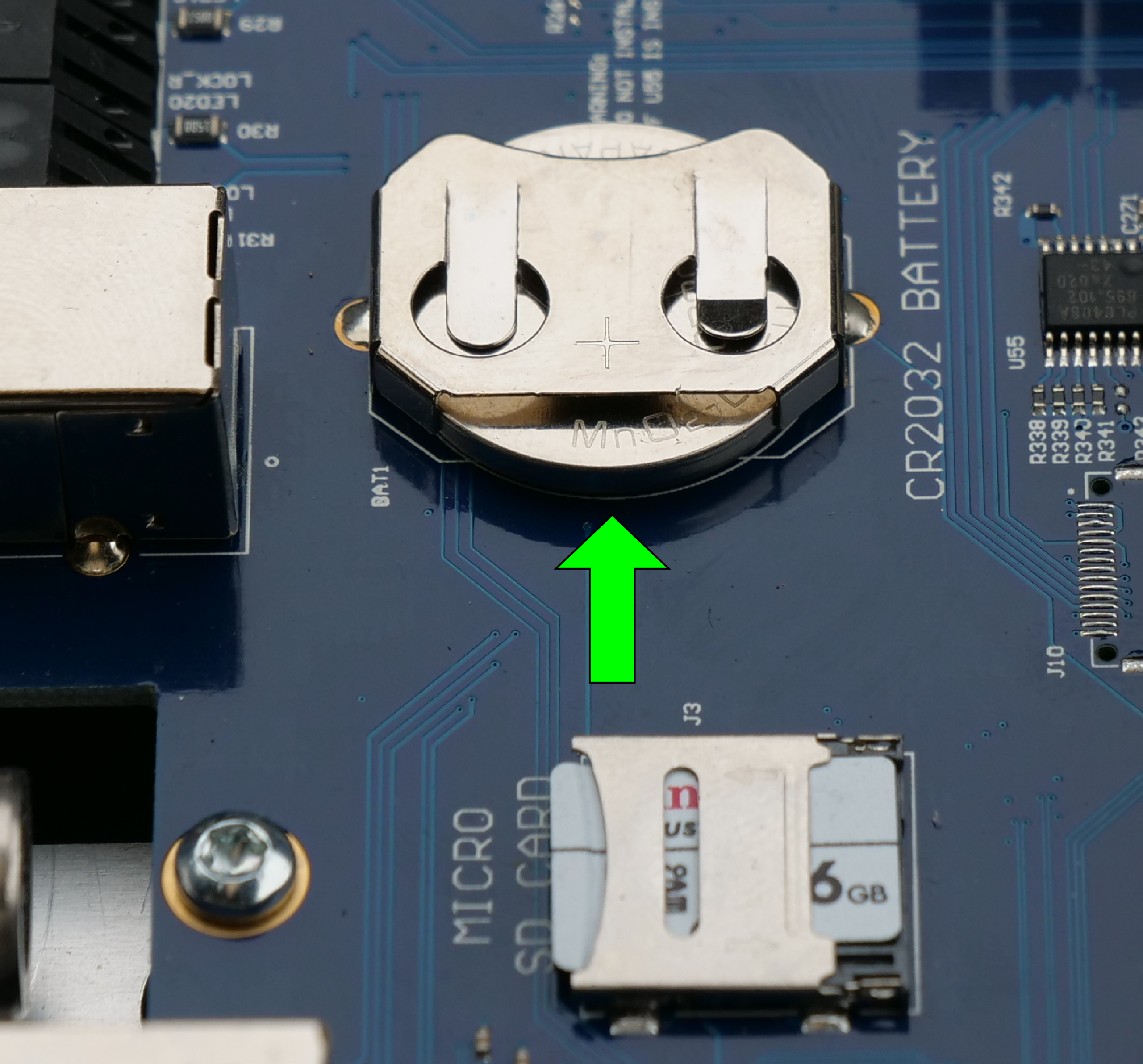
Vervang de knoopcelbatterij
Zoek het compartiment voor de knoopcel op de besturingskaart. Schuif de oude batterij voorzichtig uit de bevestigingsklem. Plaats de nieuwe batterij met de pluspool (+) naar boven.
Deel 3: De backplane vervangen
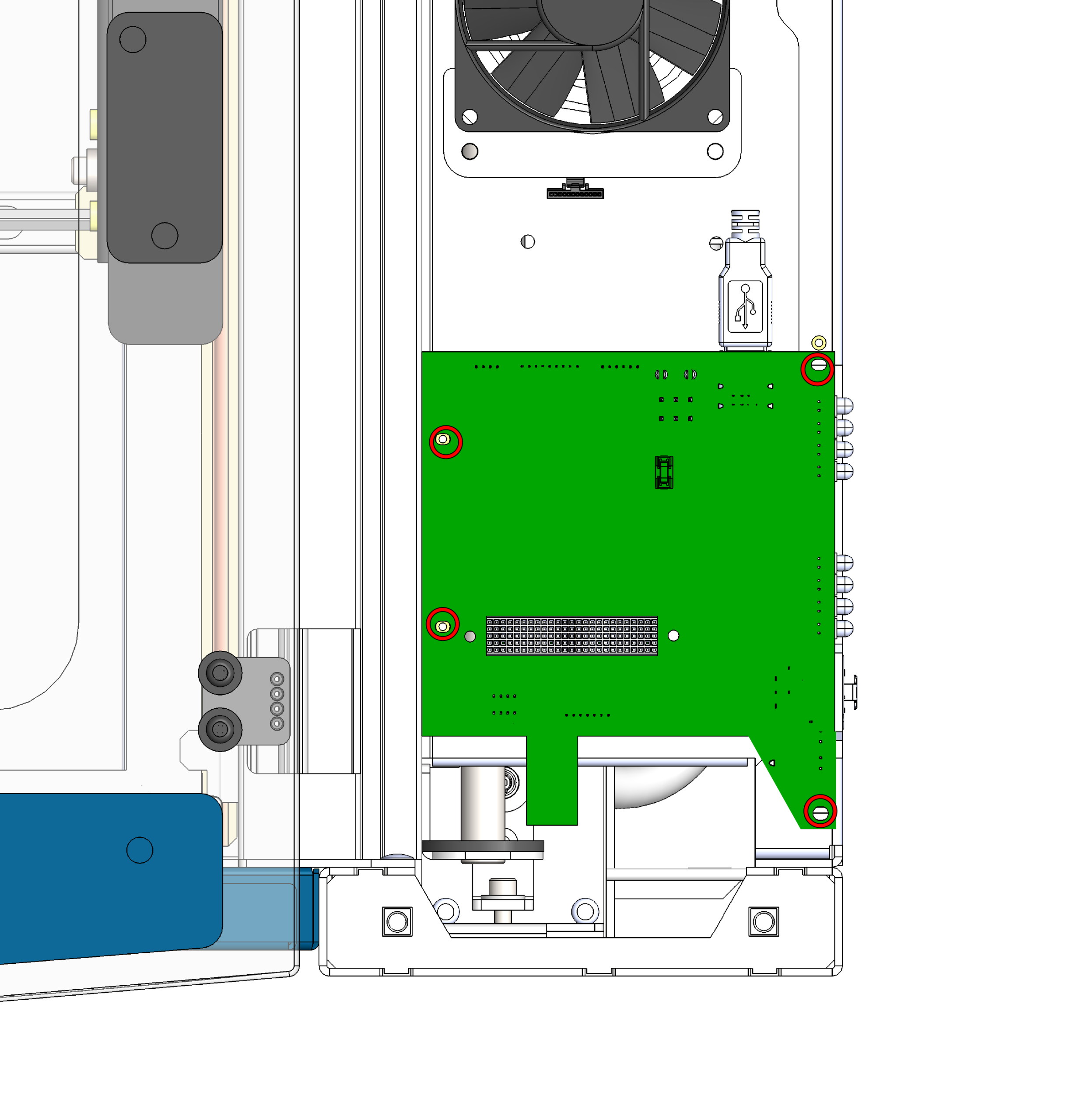
Verwijder de schroeven van de backplane
Zoek de backplane-printplaat die onder de besturingsprintplaat zit, en draai de vier schroeven los waarmee deze aan het chassis vastzit.
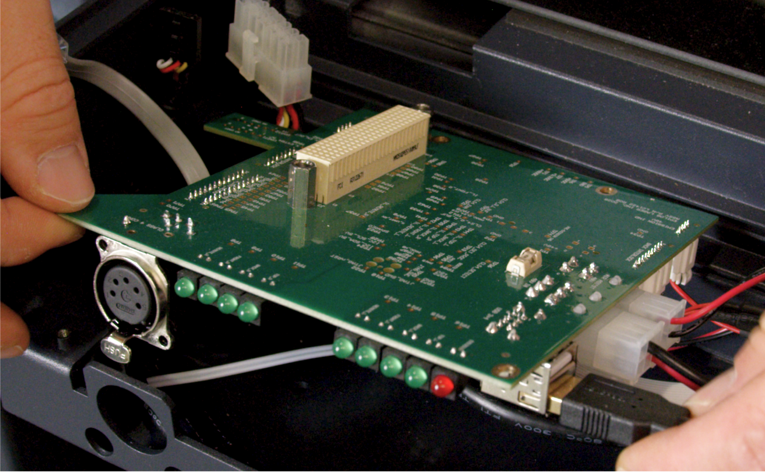
Koppel de kabels los
Zodra je de printplaat hebt losgeschroefd, koppel je voorzichtig alle kabelbomen en kabels los die erop zijn aangesloten. Zodra alles is losgekoppeld, til je de backplane uit de machine.
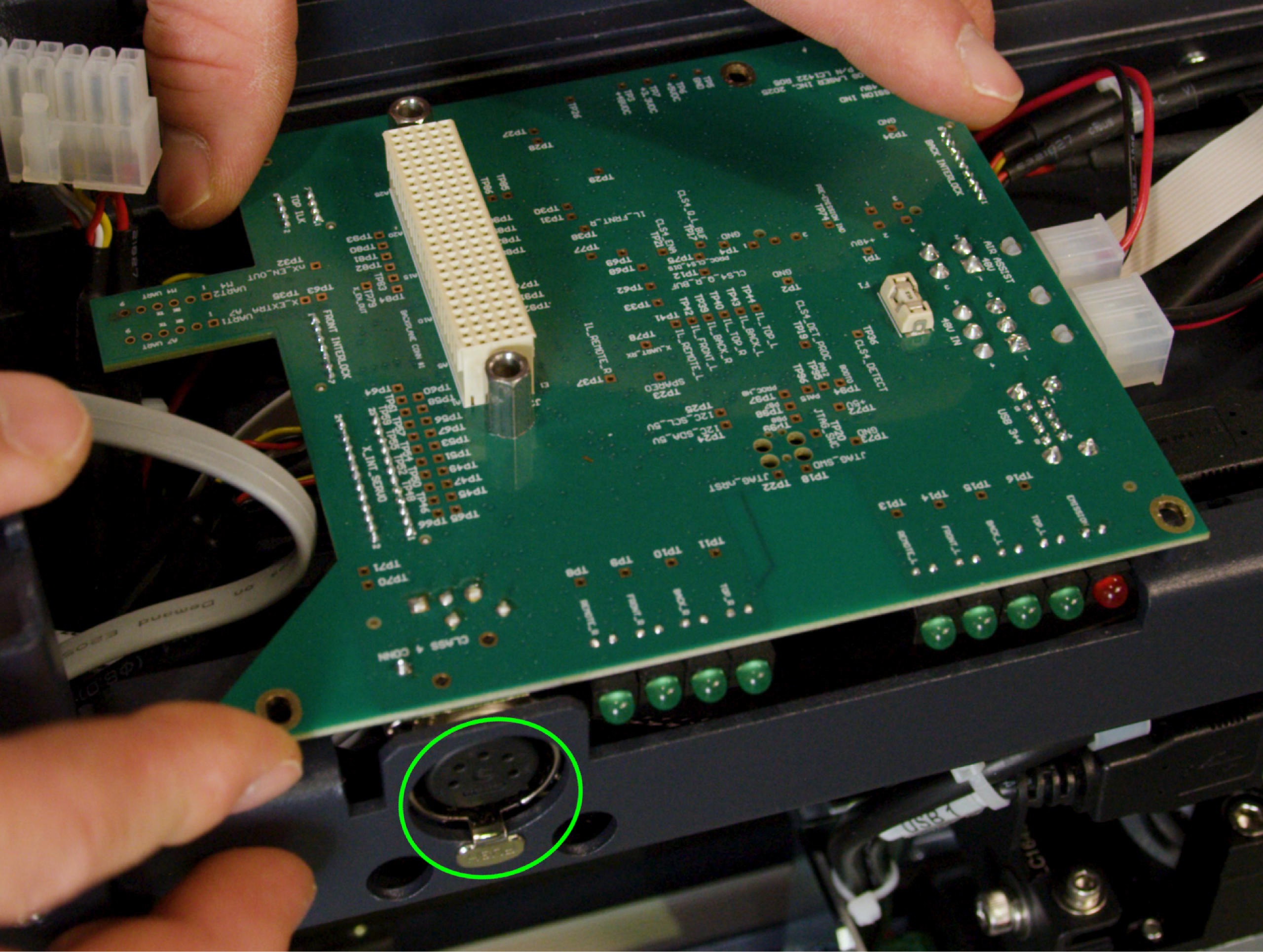
Installeer de vervangende backplane
Sluit eerst alle kabels weer aan die je in stap 9 hebt losgekoppeld. Zodra alle kabels goed zijn aangesloten, lijn je de printplaat uit en draai je de 4 schroeven weer vast om hem aan het chassis te bevestigen.
Belangrijk: De Class 4-donglepoort heeft een lipje dat precies in de uitsparing van de behuizing moet passen. Zorg ervoor dat het lipje goed in de uitsparing zit voordat je de schroeven vastdraait, om schade aan de poort of het printplaatje te voorkomen.
Deel 4: Weer in elkaar zetten en installeren
De kabelboom van de regelkaart weer aansluiten
Breng de besturingskaart (met de nieuwe SD-kaart en batterij) voorzichtig dicht bij de montageplaats en sluit de kabelbomen weer aan op de kaart.
Zitplaatsbesturingspaneel
Plaats de printplaat precies boven de schroefgaten. Druk de printplaat gelijkmatig en stevig aan, zodat deze goed vastzit aan de net geïnstalleerde achterplaat.
Beveiligde besturingskaart
Plaats de 4 schroeven weer terug en draai ze vast om de volledig op zijn plaats gezette besturingskaart aan het chassis te bevestigen.
Zijpaneel vervangen
Plaats het rechter zijpaneel van de machine weer terug en zet het vast.
Laatste controle
Sluit het apparaat weer aan op het stopcontact en zet het aan. Controleer of het touchscreen normaal opstart en of het apparaat goed initialiseert, wat aangeeft dat het nieuwe moederbord, de SD-kaart, de batterij en de backplane allemaal goed met elkaar communiceren.