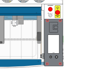
La sécurité avant tout : assurez-vous que le système laser est complètement hors tension et que le cordon d'alimentation principal est débranché de la prise murale avant de toucher ou de déconnecter tout composant électronique interne. Ne touchez aucun composant exposé du bloc d'alimentation.
Important : la carte de commande, le fond de panier et les autres composants électroniques sont sensibles aux décharges électrostatiques (ESD). Portez toujours un bracelet antistatique relié à la masse du châssis métallique nu de la machine avant de manipuler ces composants afin d'éviter tout dommage.
1re partie : Démontage de la carte de commande
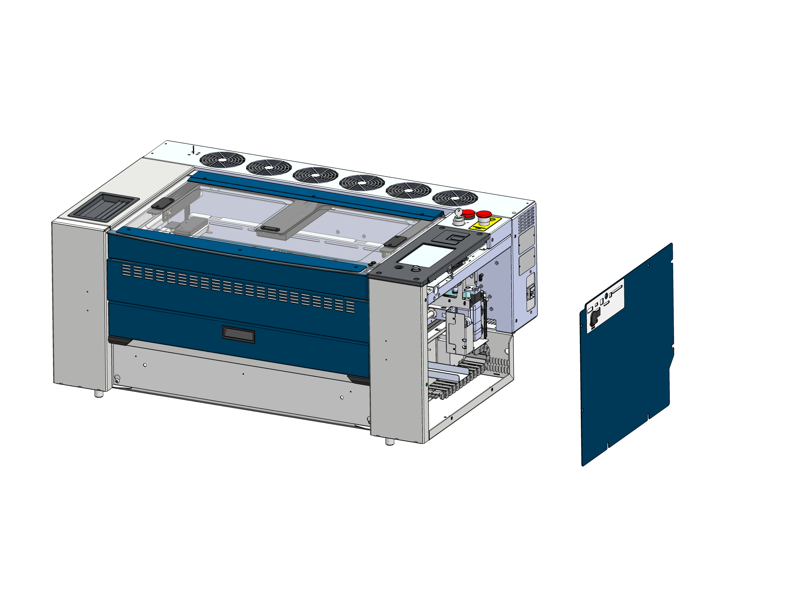
Retirer le panneau latéral
Repérez et retirez le panneau latéral droit du châssis du laser afin d'accéder aux composants électroniques.
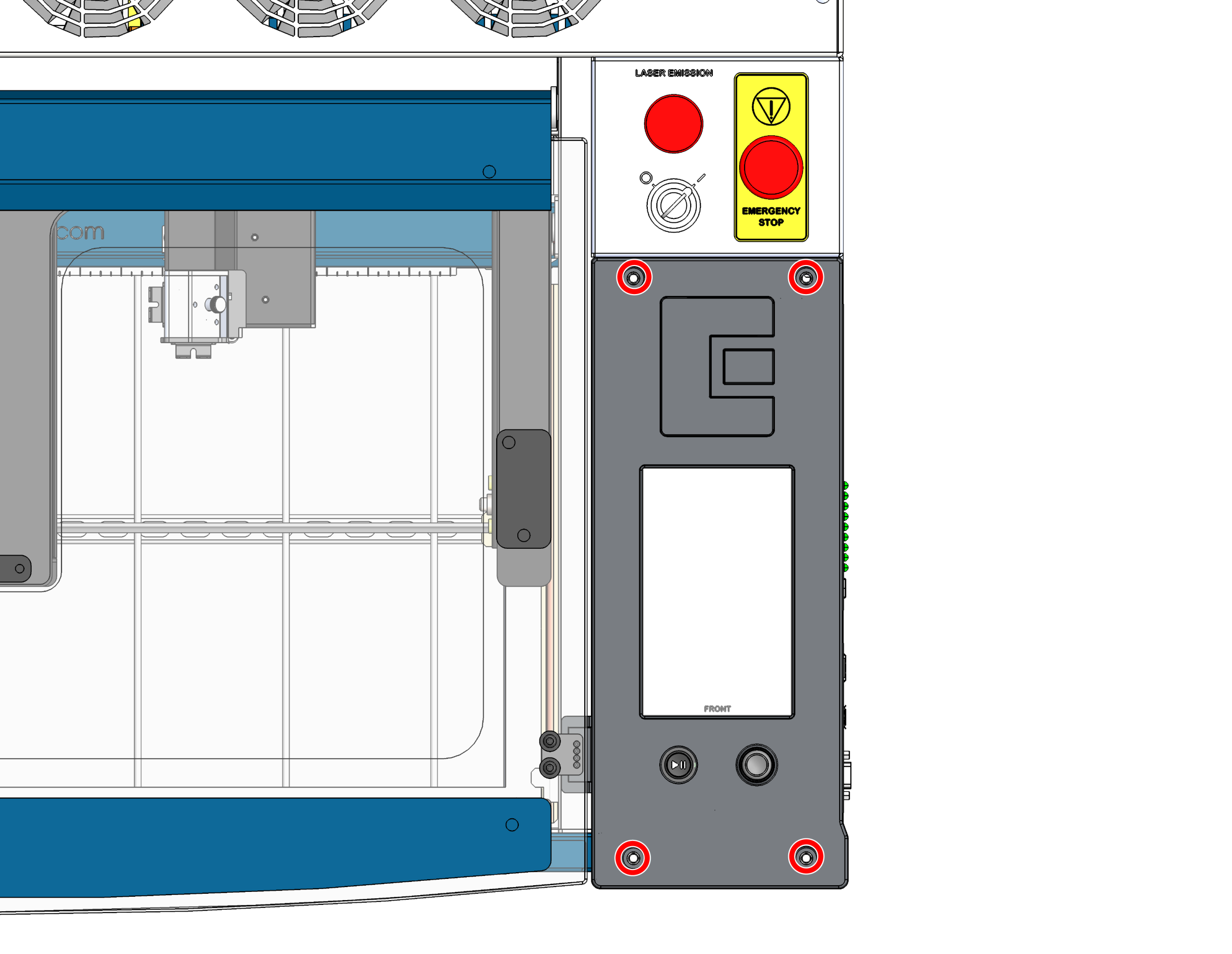
Retirer les vis du panneau de commande
Retirez les 4 vis qui fixent la carte de commande au châssis.
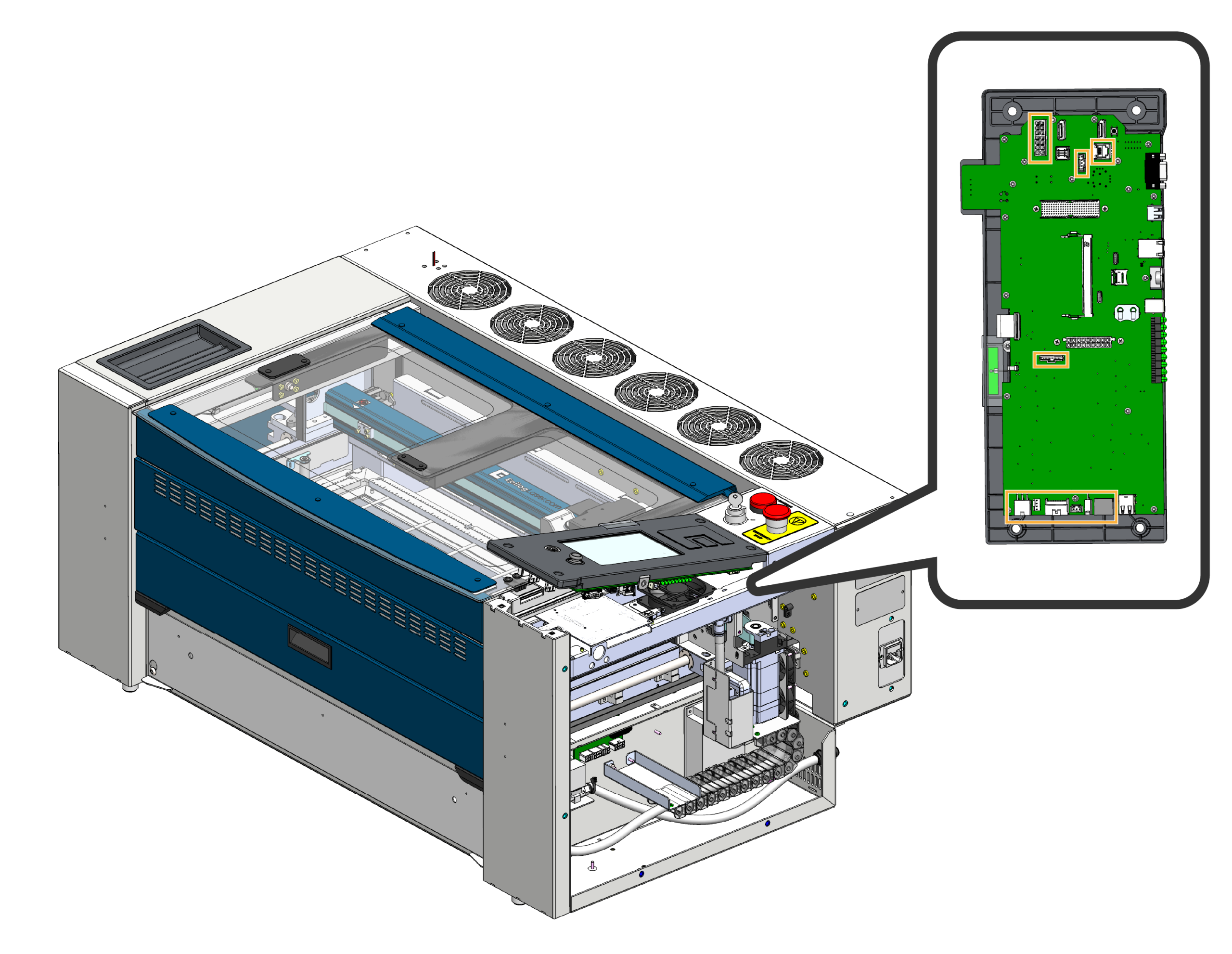
Débranchement du faisceau de câbles
Soulevez délicatement l'avant de la carte de commande et débranchez les faisceaux de câbles qui y sont connectés.
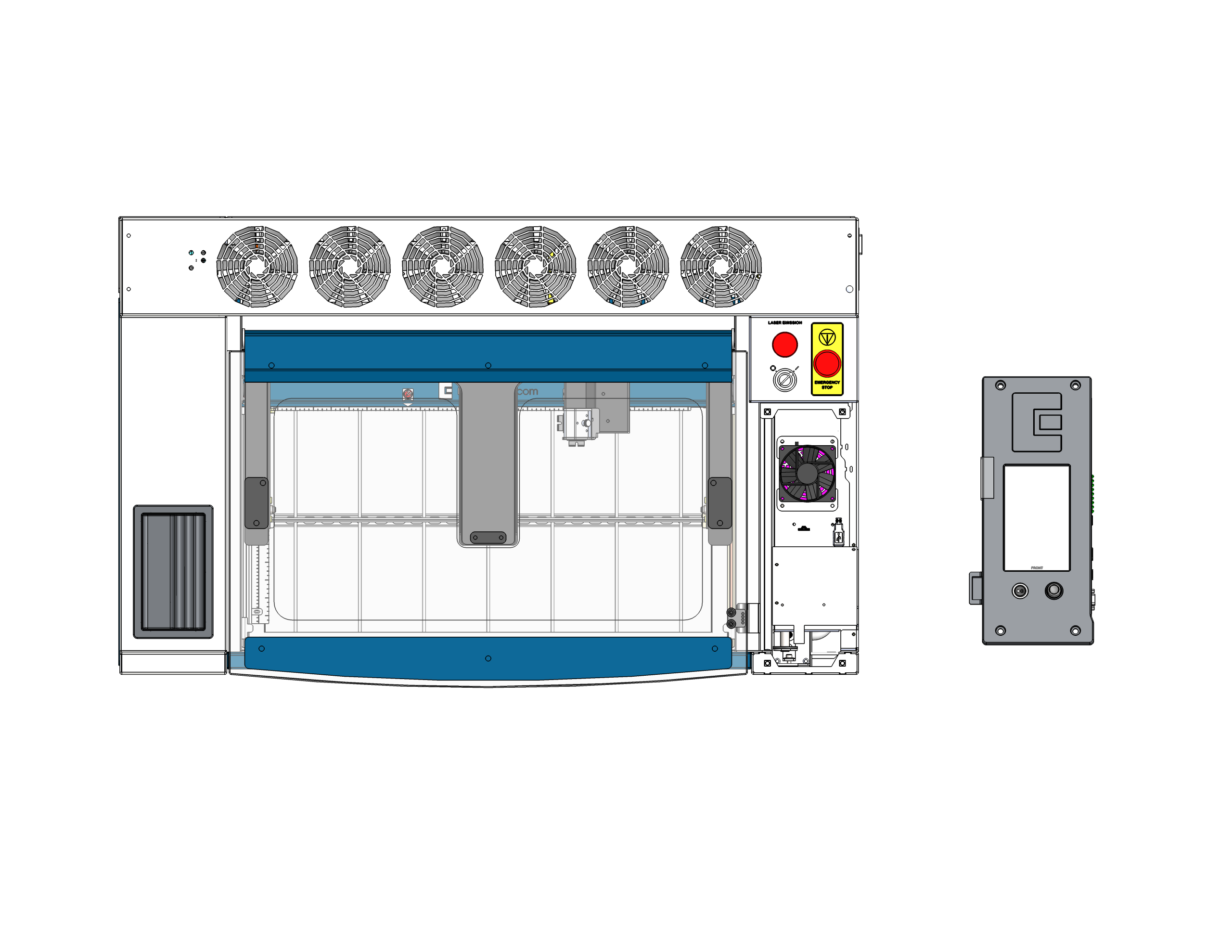
Retirer la carte de commande
Retirez la carte de commande de la machine et déposez-la entièrement. Posez-la face vers le bas sur une surface sûre et antistatique. Important : veillez à ce que le joystick dépasse du bord de la surface ou soit posé sur un matériau souple afin qu’il ne soit pas écrasé ou endommagé pendant que vous intervenez à l’arrière de la carte.
Partie 2 : Remplacement de la carte SD et de la pile bouton
La carte de commande étant bien posée, face vers le bas, vous pouvez désormais accéder facilement à la carte SD et à la pile bouton situées sur la carte, et les remplacer.
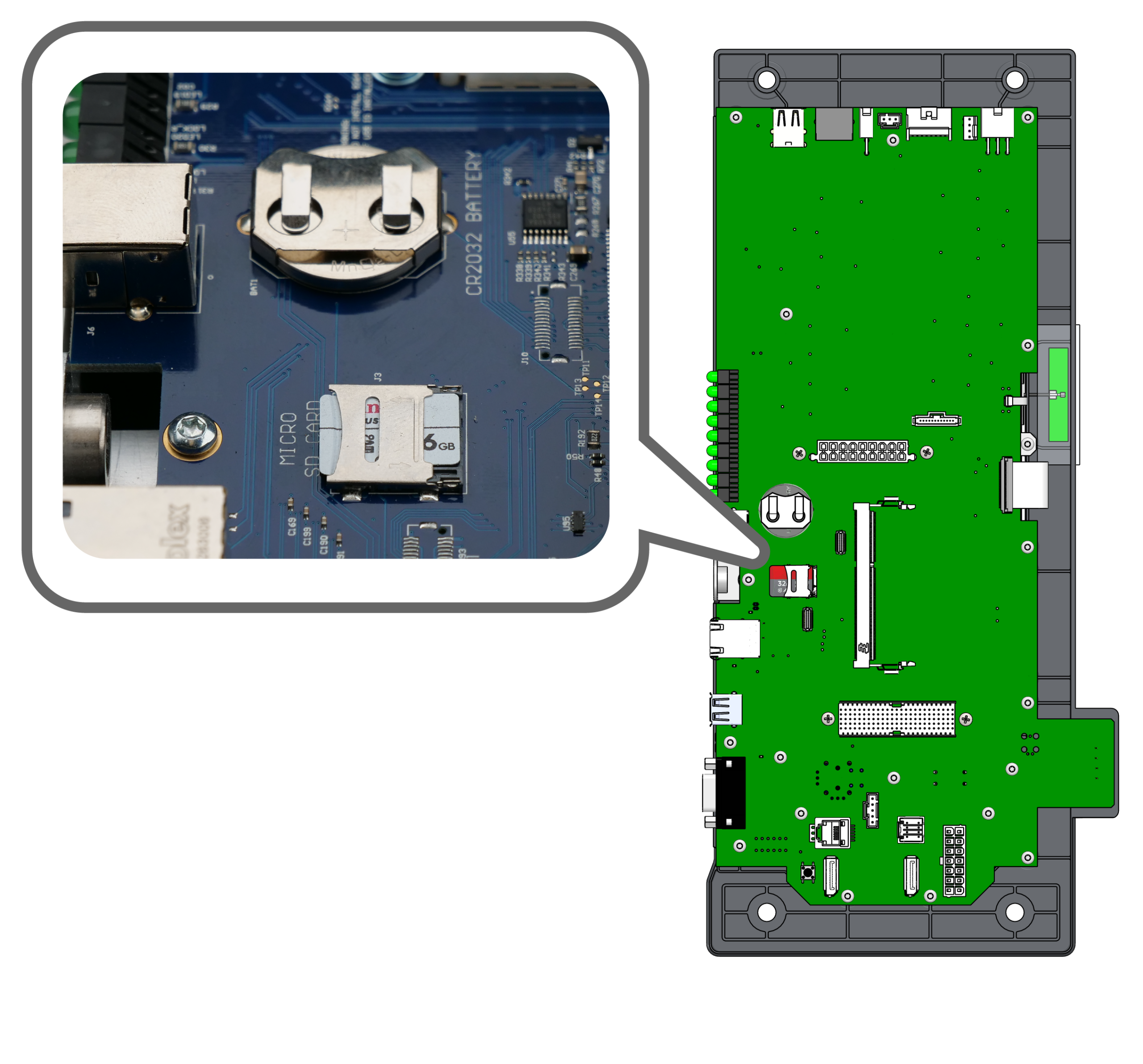
Localiser les composants
Repérez la carte Micro SD et le compartiment de la pile bouton CR2032 à l'arrière de la carte de commande.
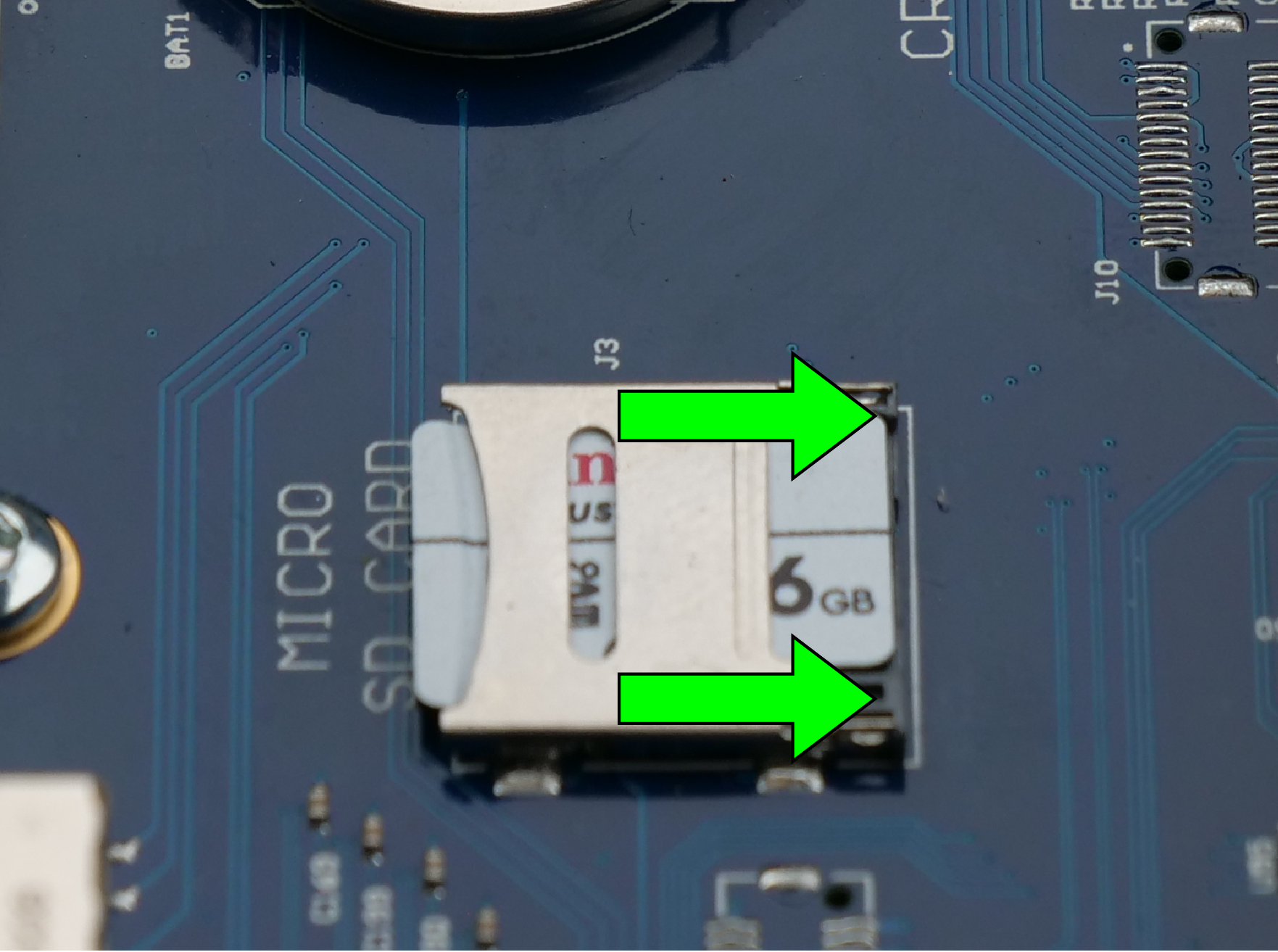
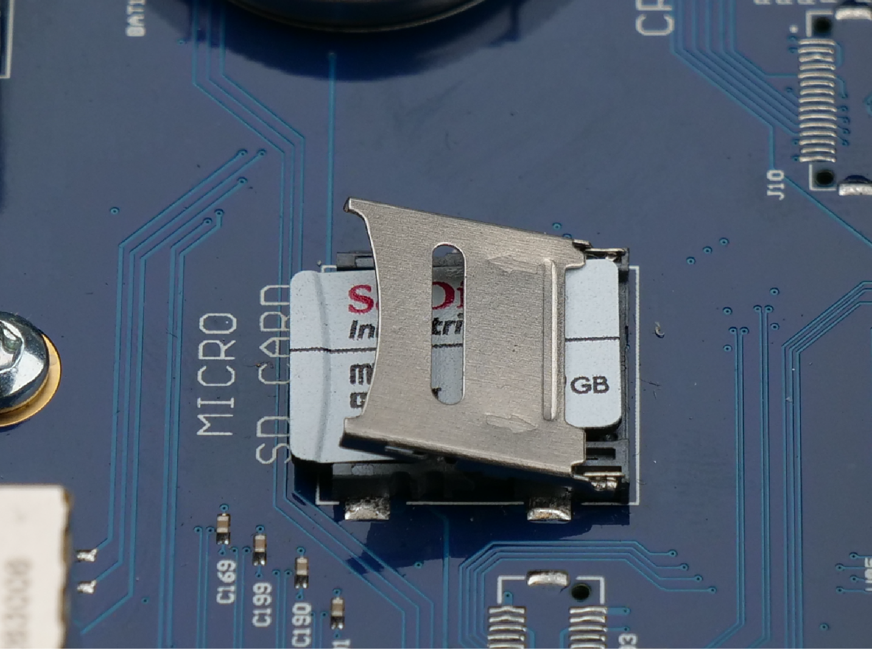
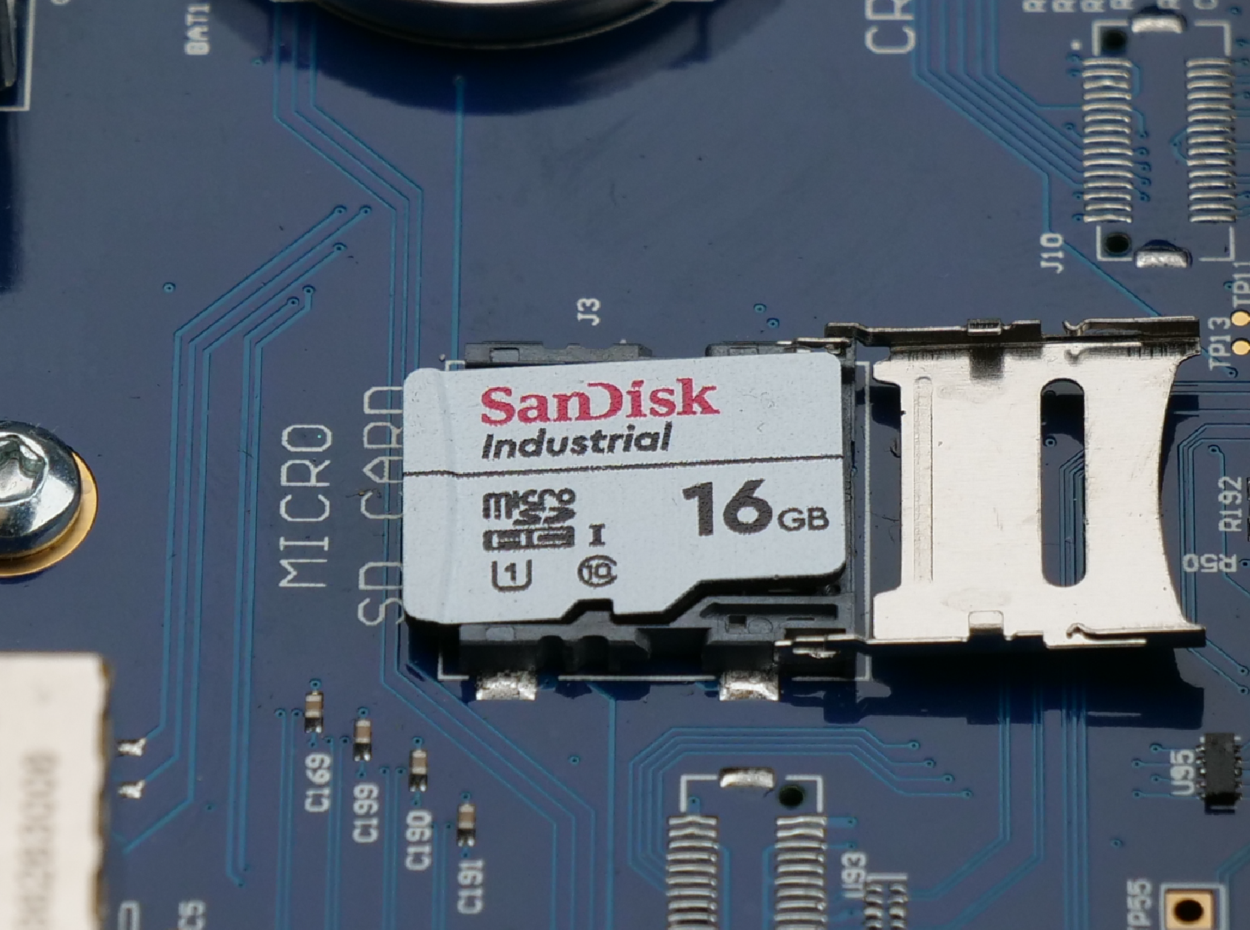
Remplacer la carte SD
Cliquez sur les onglets de l'image pour consulter les étapes de remplacement :
- Déverrouillage : Faites glisser le loquet métallique vers l'intérieur (dans le sens de la flèche) pour le déverrouiller.
- Pour ouvrir : soulevez le loquet métallique déverrouillé vers le haut pour accéder à la carte SD.
- Remplacement : retirez l'ancienne carte SD, insérez la nouvelle, puis refermez le loquet et faites-le glisser vers l'extérieur pour le verrouiller.
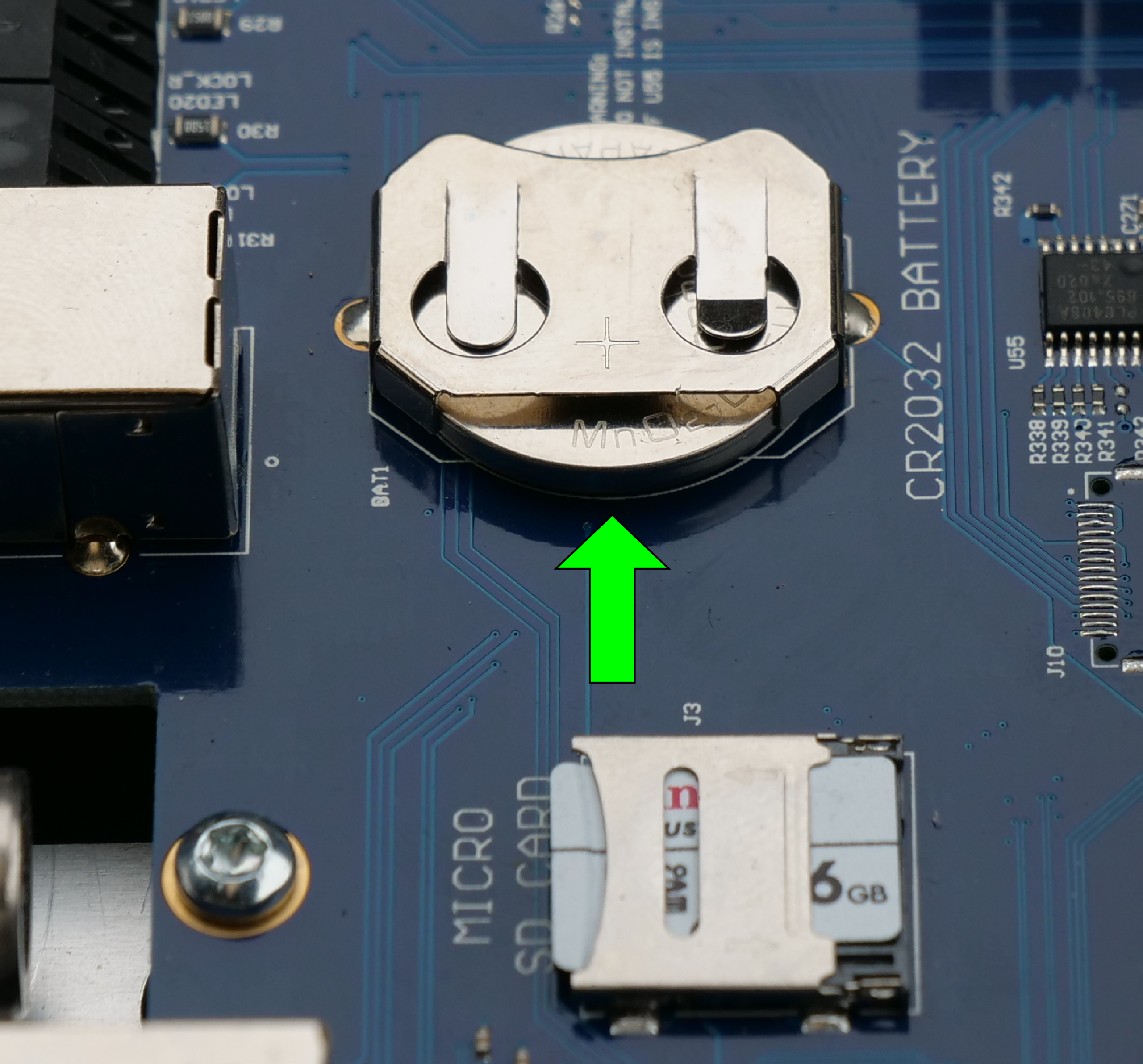
Remplacer la pile bouton
Repérez le compartiment de la pile bouton sur la carte électronique. Retirez délicatement l'ancienne pile de son clip de fixation. Insérez la nouvelle pile en veillant à ce que le pôle positif (+) soit tourné vers le haut.
3e partie : Remplacement du fond de panier
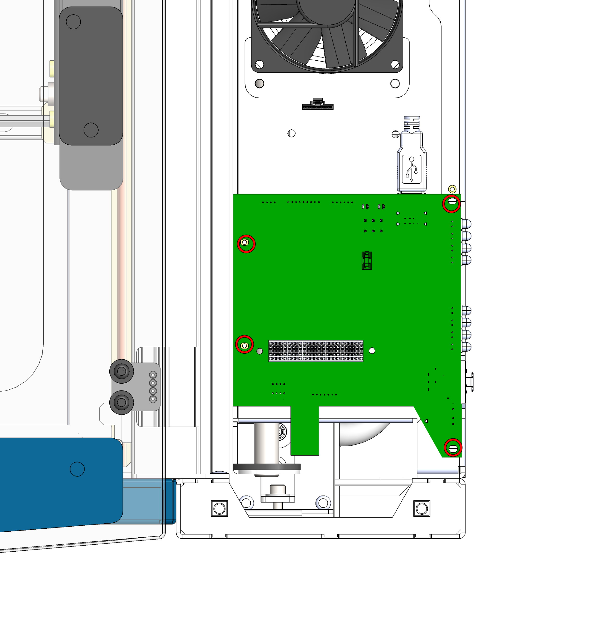
Retirer les vis du fond de panier
Repérez la carte de fond de panier située sous la carte de commande, puis retirez les quatre vis qui la fixent au châssis.
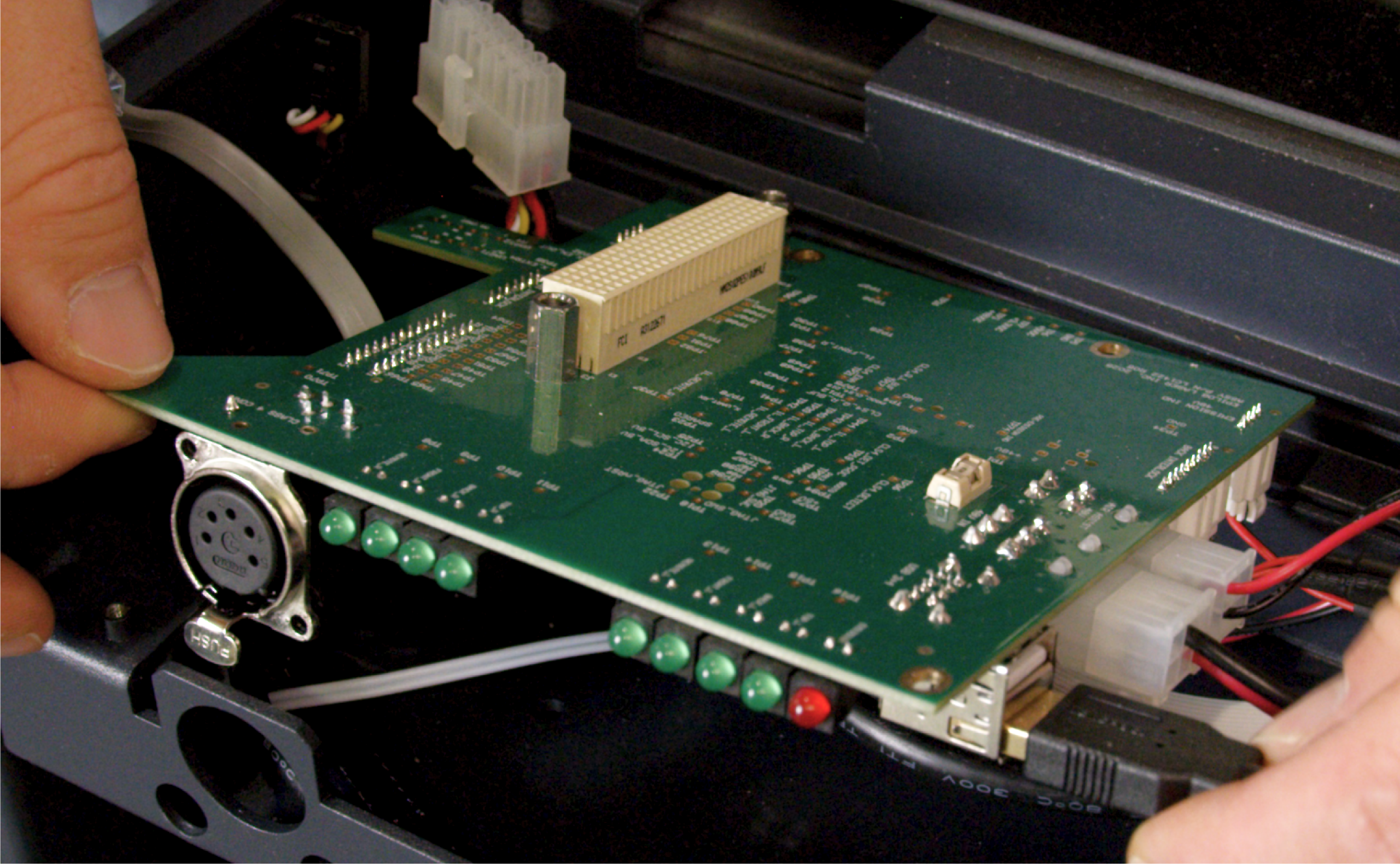
Débrancher les câbles
Une fois la carte dévissée, débranchez avec précaution tous les faisceaux de câbles et les câbles qui y sont raccordés. Une fois tous les branchements déconnectés, retirez la carte mère de l'appareil.
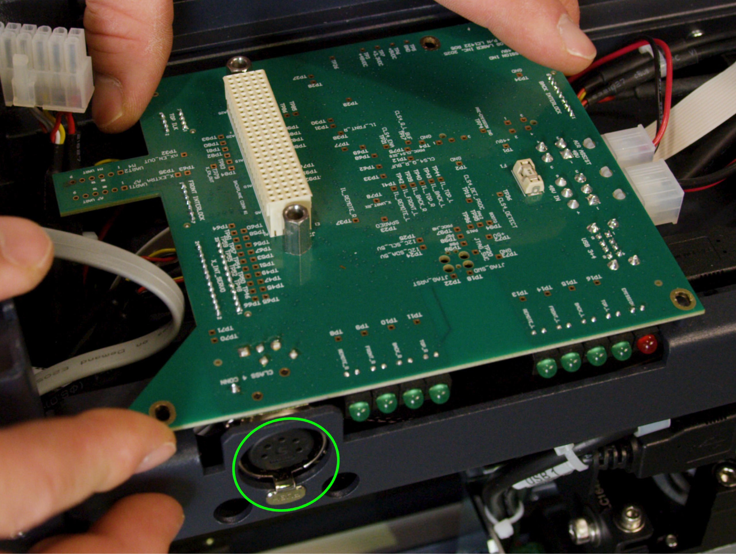
Installer le fond de panier de remplacement
Commencez par rebrancher tous les câbles que vous avez débranchés à l'étape 9. Une fois tous les câbles correctement branchés, alignez la carte et revissez les 4 vis pour la fixer au châssis.
Important : le port pour clé de classe 4 comporte une languette qui doit être alignée avec la découpe du châssis. Assurez-vous que la languette est correctement positionnée dans la découpe avant de serrer les vis afin d'éviter d'endommager le port ou la carte.
4e partie : Remontage et installation
Raccordement du faisceau de câbles de la carte de commande
Approchez avec précaution la carte de commande (équipée de sa nouvelle carte SD et de sa batterie) de la zone de montage, puis rebranchez les faisceaux de câbles à la carte.
Carte de commande des sièges
Centrez la carte de commande directement au-dessus des trous de vis. Appuyez de manière uniforme et ferme pour vous assurer que la carte est bien fixée au fond de panier nouvellement installé.
Carte de commande sécurisée
Remettez en place et serrez les 4 vis pour fixer solidement la carte de commande, une fois bien en place, au châssis.
Remplacer le panneau latéral
Remettez en place et fixez le panneau latéral droit de la machine.
Vérification finale
Rebranchez l'appareil sur la prise murale et mettez-le sous tension. Vérifiez que l'écran tactile démarre normalement et que l'appareil s'initialise correctement, ce qui indique que la nouvelle carte mère, la carte SD, la batterie et le fond de panier communiquent tous correctement entre eux.