Estimated time: 30-45 minutes • Skill: Advanced
This procedure outlines the proper method for adjusting belt tracking on the belt control version of the X-Axis rail. Correct belt alignment ensures stable belt tracking, smooth carriage travel, and optimal engraving performance.
Warning: Only perform this procedure if absolutely necessary. Improper belt tracking can cause severe motion issues, drive errors, or premature belt wear. Follow the steps carefully and make small adjustments as needed.
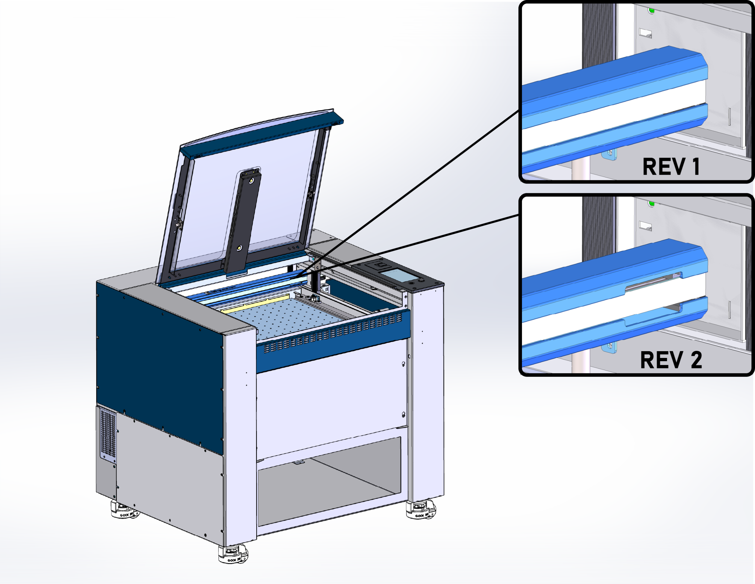
Identifying X-Axis Rail Version
Before you begin, determine which version of the X-Axis rail is installed in your machine. Check the right side of the X-Axis rail: if there is no cutout, you have Revision 1 and must follow the alternative procedure; if there is a cutout, you have Revision 2, and can follow the procedure below.
Setting Belt Tracking and Tension
-
Prepare the machine
Power off the laser system and unplug it from the electrical outlet. Open the lid and ensure the work area is clear. Have a second person available to assist with manual carriage movement during adjustments.
-
Remove the side panels
Remove the Right and Left Side panels.

Figure 1. Removing right and left panels. -
Check the main belt tension
The main X-Axis belt should be set slightly under tension. Insert the belt tension tool into the center of X-Axis belt and check the tension. The tensioner tool O-ring should be barely visible when fully inserted into the center of the X-Axis belt.
Figure 2. Main belt tension reference. 
Figure 3. Low tension on belt. -
Adjust main belt tension
To adjust the X-Axis belt tension, loosen the idler locking screws, and use the belt tension adjustment to set the belt tension slightly low.
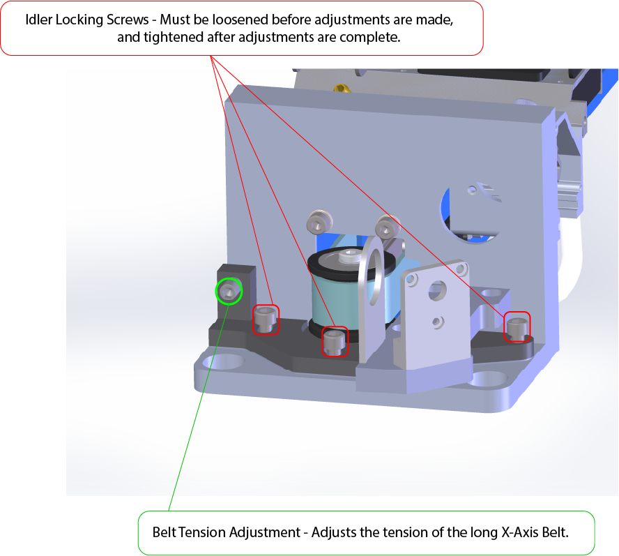
Figure 4. Idler pulley adjustments. -
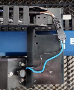
Loosen the reducer locking screws
There are four screws on each side of the reducer. Loosen them evenly to allow adjustment.
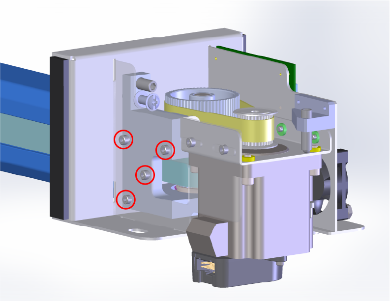
Figure 5. Reducer locking screw locations FRONT RIGHT. 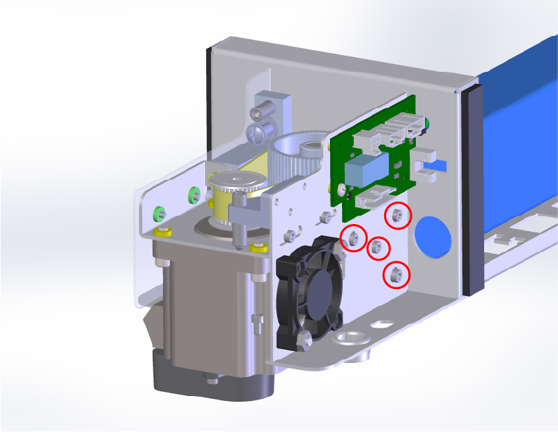
Figure 6. Reducer locking screw locations BACK RIGHT. -
Adjust the reducer belt tracking
Use the reducer adjustment to align the belt so it stays centered on the lower (bottom) pulley of the reducer assembly.
Move the carriage manually along the X-Axis to simulate a job running and observe belt tracking. Make small adjustments until the belt remains centered throughout the full range of motion.
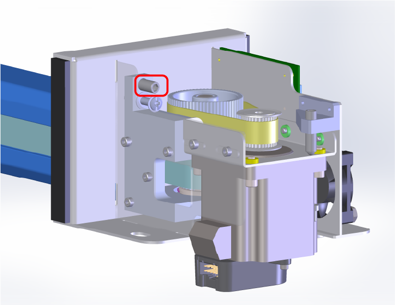
Figure 6. Reducer belt tracking adjustment. 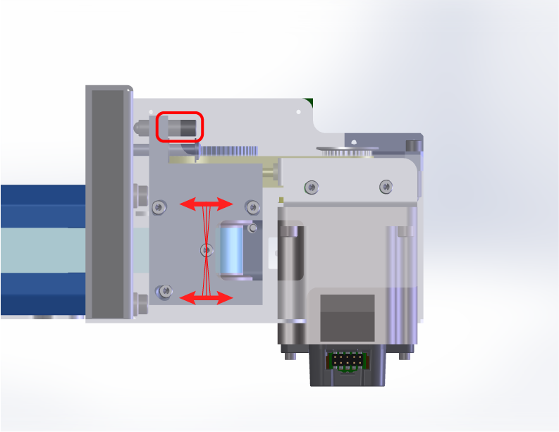
Figure 7. Reducer belt tracking adjustment. Note: The reducer adjustment screw is a fine thread adjustment, you must loosen the locking screws before making any adjustments. The reducer adjustment changes the angle of the reducer pulley. Tightening adjustment will loosen the tension on the two belts and force the X-Axis belt tracking downward. Loosening will tighten the tension of the belts and force the X-Axis belt tracking upward. -
Verify or adjust the main X-Axis belt tension
Confirm that the main belt tension is correct before continuing to the next steps. The O-ring on the tensioner tool should be flush with the body of the tool when inserted into the center of the X-Axis belt.
Figure 7. Verifying main belt tension. 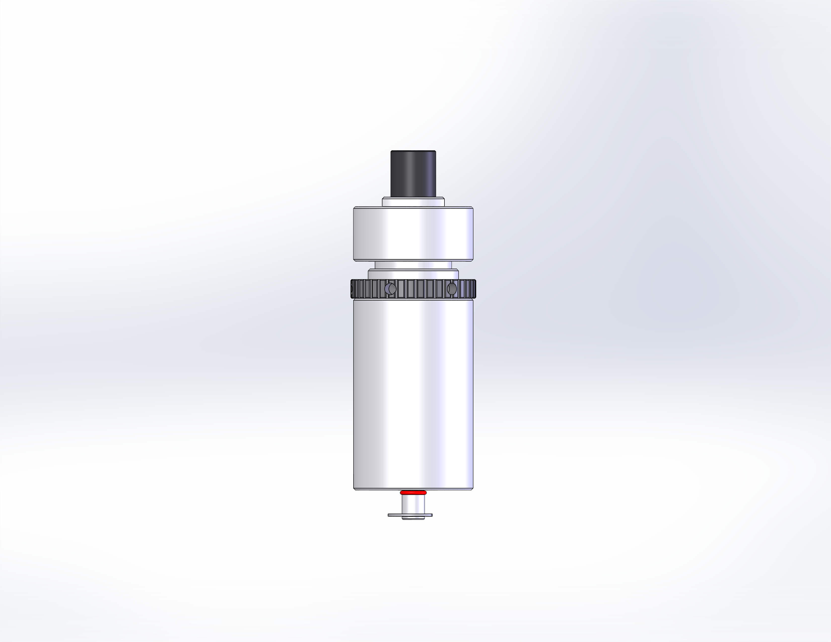
Figure 8. Correct tension on belt. - Secure the reducer adjustments
Tighten the locks for both the belt tension and the reducer pulley position once alignment is correct.
Figure 9. Reducer locking screw locations FRONT RIGHT. Figure 10. Reducer locking screw locations BACK RIGHT. - Loosen the X-Axis motor mounting screws
Loosening the motor screws will allow for proper tracking adjustment between the motor pulley and reducer belt.
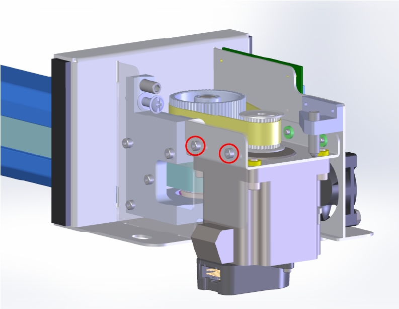
Figure 10. Motor mounting screw locations FRONT RIGHT. 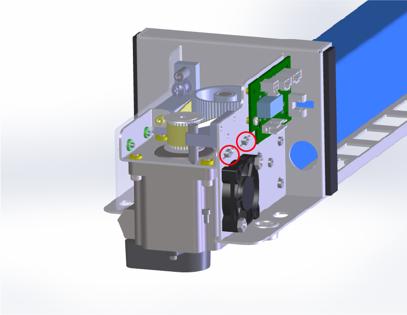
Figure 11. Motor mounting screw locations BACK RIGHT. - Center the reducer belt on the motor pulley
Use the motor tracking adjustment to align the belt so it runs true on the motor pulley.
Move the carriage manually along the X-Axis. Make small adjustments until the belt remains centered throughout the full range of motion.
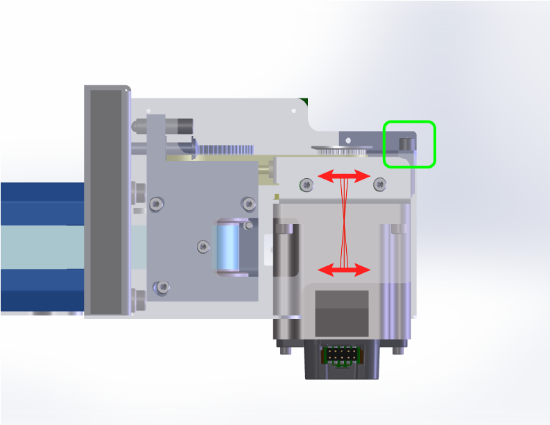
Figure 10. Motor tracking adjustment and angles FRONT RIGHT. 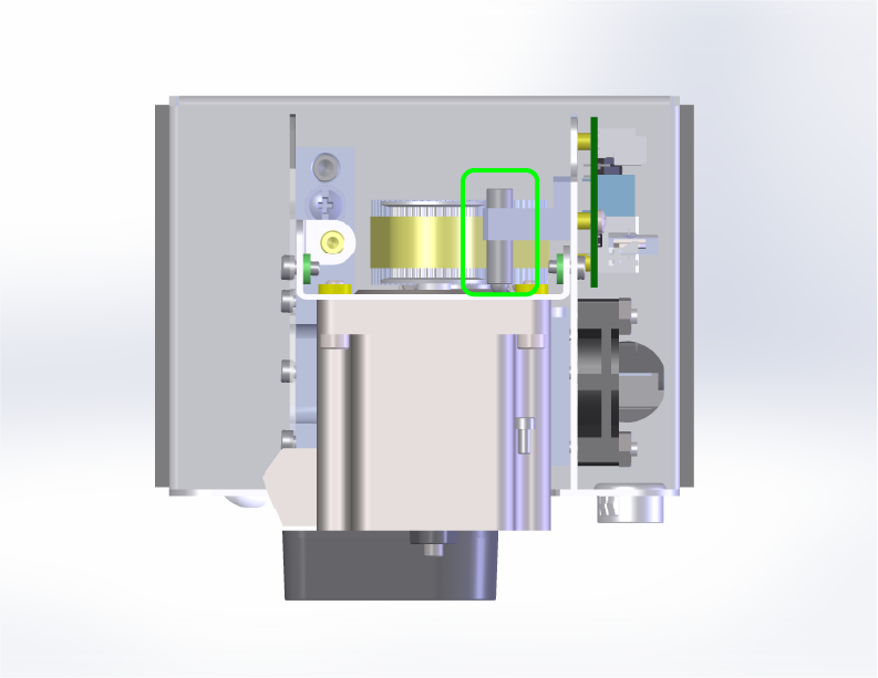
Figure 11. Motor tracking adjustment RIGHT SIDE. Note: The motor tracking adjustment screw is a fine thread adjustment, you must loosen the locking screws before making any adjustments. Tightening will force the belt to track downward. Loosening will force the belt to track upward. If there is a gap between the adjustment screw and motor bracket, you may need to gently pull the motor assembly towards you.- Check the reducer belt tension
The reducer belt should have approximately 1/8 inch (3 mm) of deflection when pressed at the midpoint. Adjust the tension if needed.
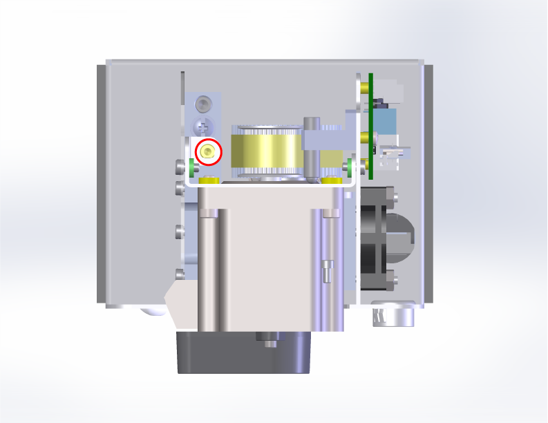
Figure 12. Reducer belt tension check. 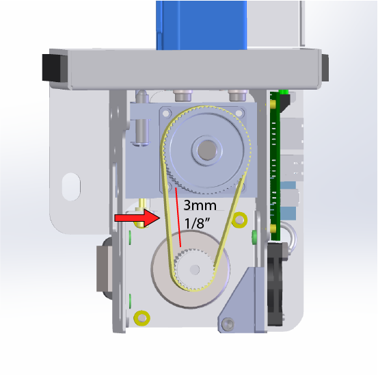
Figure 13. Reducer belt tension measurement. - Tighten the X-Axis motor mounting screws
Once all alignment and tension checks are correct, securely tighten the motor mounting screws.
Figure 14. Motor mounting screw locations FRONT RIGHT. Figure 15. Motor mounting screw locations BACK RIGHT. - Final check
With all adjustment locking screws secure, check the belt tracking at the reducer pulley and motor pulley. The belt should be tracking in the middle of the pullies and the tension of the belts should be correct.
- Reinstall the side panels
Reattach the Right and Left Side panels to complete the procedure.
Figure 16. Reinstalling right and left panels. Was this helpful?
Thanks for your feedback! - Secure the reducer adjustments