Introduction
This document provides concise, step‑by‑step instructions for removing and installing the X‑Axis linear guide (IKO rail) on Fusion Edge, Maker, and Pro 24/36 engravers. Read the entire procedure before beginning, observe all safety precautions (power off and disconnect), and have the required hand tools ready. Follow each step in order to avoid damage to components.
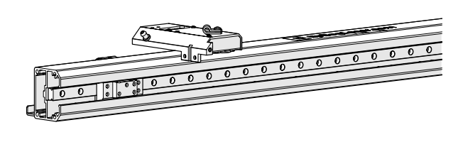
Linear Guide Removal
-
- Turn off the engraver.
- Disconnect the engraver from power source.
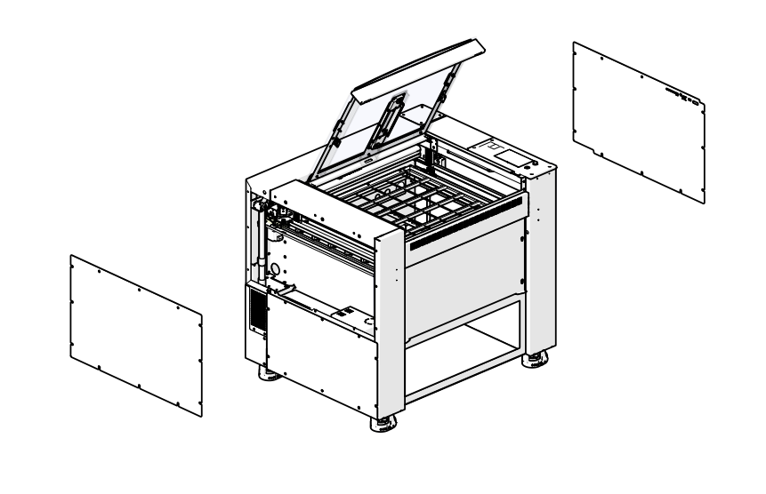
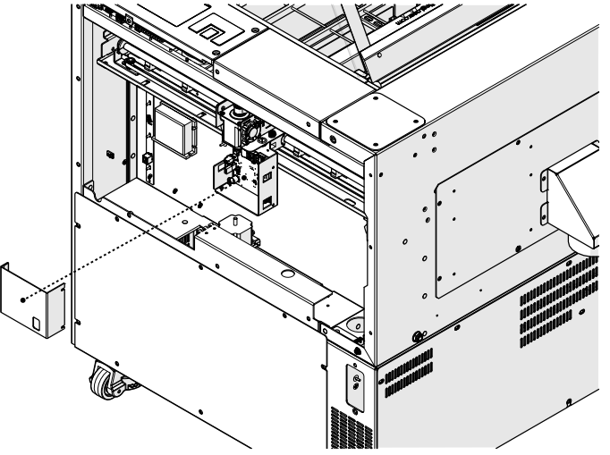
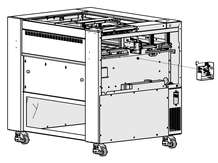
- Remove the left and right panels of the engraver.
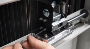
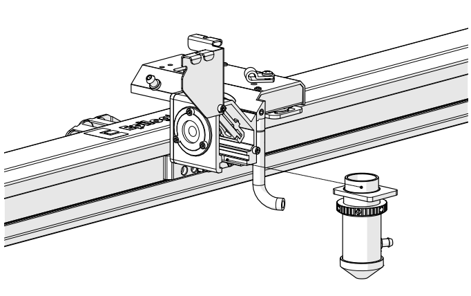
- Loosen and remove the lens tube assembly from the x-axis assembly.
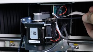
- Remove the x-axis drive board cover.
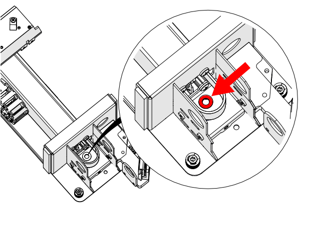
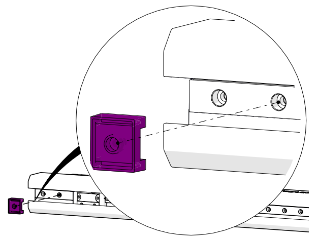
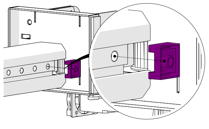
- Disconnect the air assist tubing from the right side of the x-axis assembly.
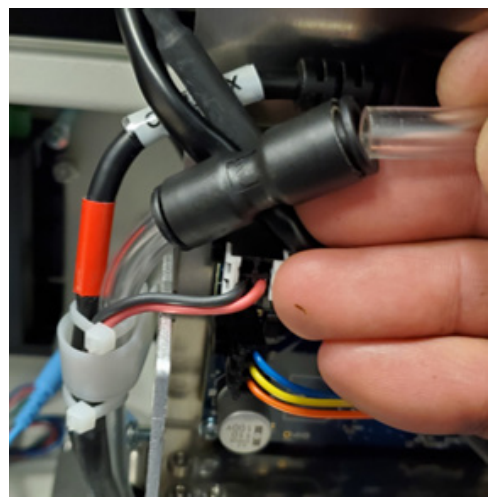 Note: The AA tubing is held by a tubing coupler. To remove the tubing, press the tubing into the fixture. Then, while holding the retaining ring tight to the fixture, pull the AA tubing away from it.
Note: For Fusion Maker engravers, proceed to 10.
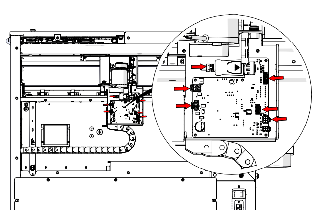
- Remove the six (6) electrical connections on the drive board.
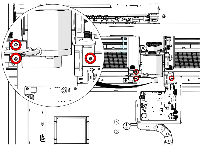
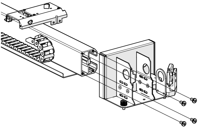
- Loosen and remove the three (3) Phillips screws that secure the x-axis drive board mounting bracket to the x-axis assembly.
- Remove the x-axis drive board and housing.
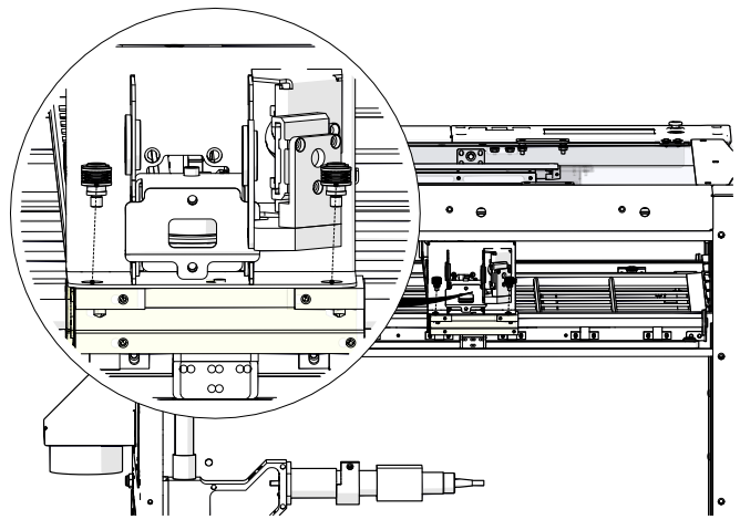
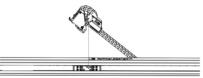
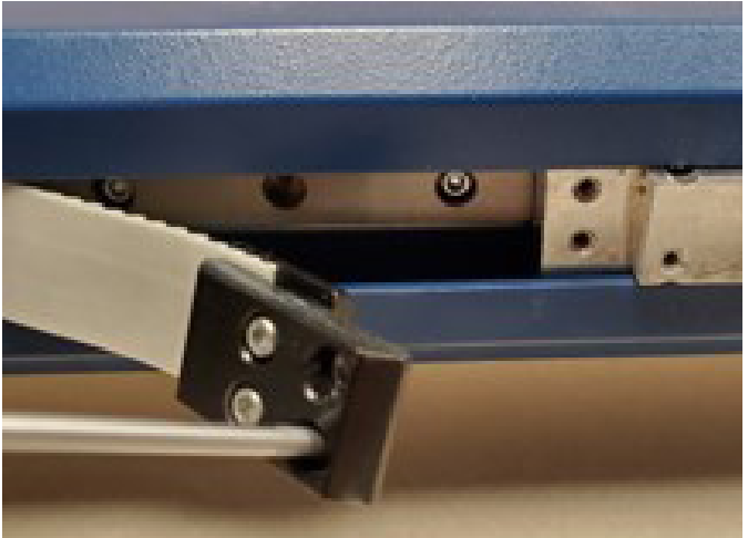
- Disconnect the bellows on the left and right side of the engraver.
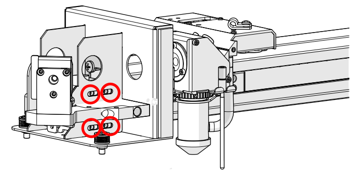
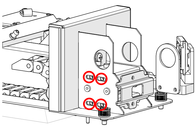
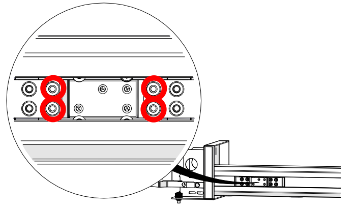
- Remove the four (4) fasteners that secure the x-axis assembly to the y-axis bearings. There are two (2) on the right side and two (2) on the left side.
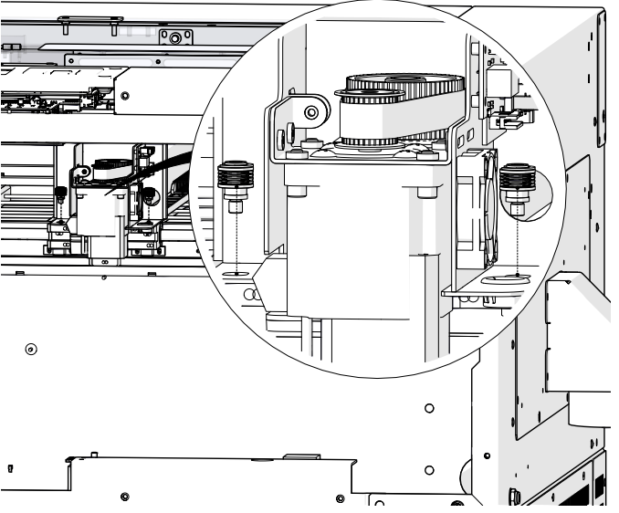
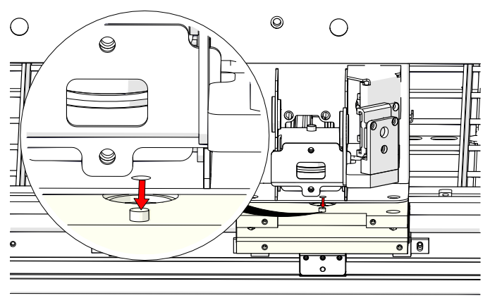
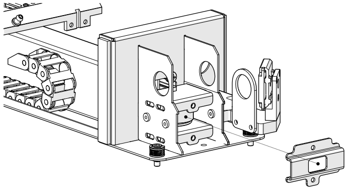
- Gently lift on the x-axis assembly to free it from the locator pins on the y-axis bearing blocks.
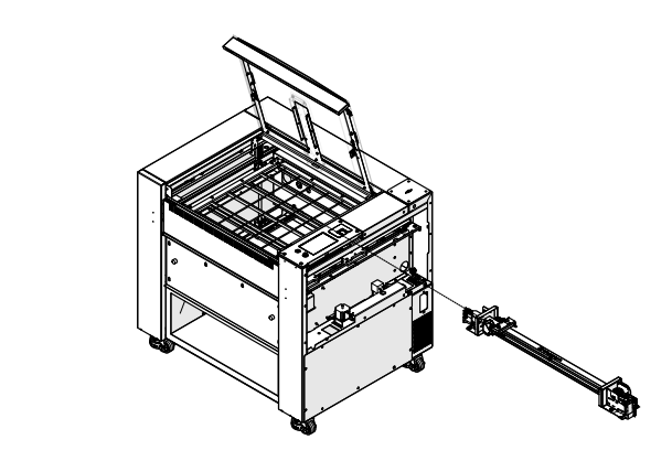
- Slide the x-axis assembly out of the cabinet through the right side of the engraver.
- Loosen and remove the 3/32” Allen screw that secures the autofocus switch to the carriage assembly.
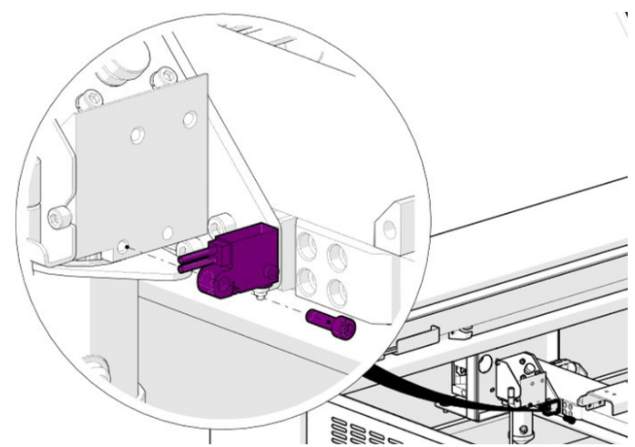
- Remove the autofocus switch.
- Loosen and remove the four (4) 3/32” Allen screws that secure the carriage assembly to the carriage assembly mounting plate.
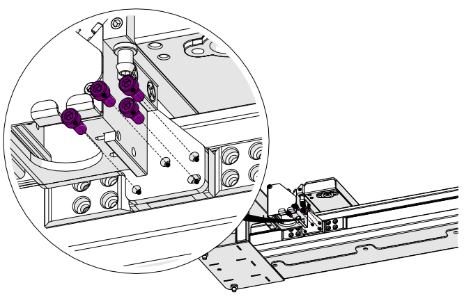
- Remove the carriage assembly.
- Loosen, but do not remove the eight (8) 7/64” Allen screws on the x-axis idler assembly.
- Loosen and remove the two (2) 7/64” tensioner screws on the idler assembly body.
- Remove the idler assembly front cover.
- Remove the top four (4) 7/64” Allen screws on the x-axis idler assembly.
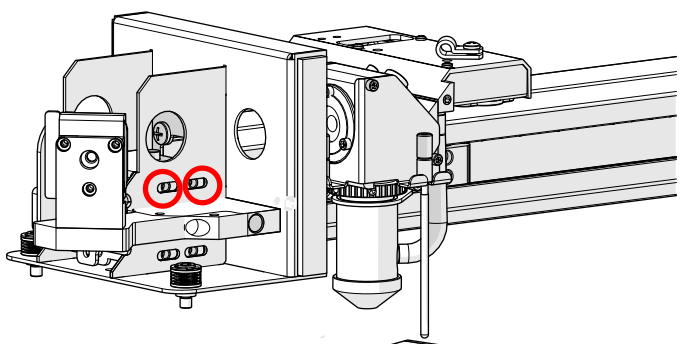
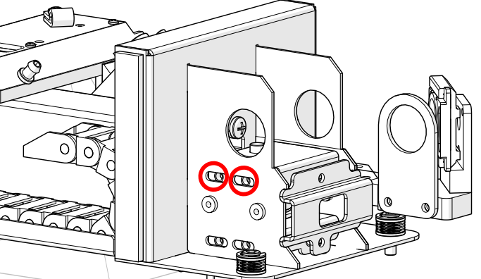
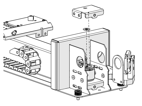
- Remove the upper tensioner bracket and the upper Delrin washer on top of the idler pulley.
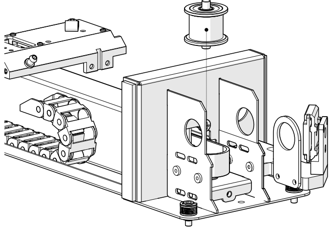
- Remove the idler pulley, ensuring that the Delrin washer beneath it stays in place.
- Loosen and remove the four (4) 3/32” screws that secure the x-axis belt clamps to the linear guide slider block.
- Remove the left and right x-axis belt clamps from inside the x-axis assembly.
- Loosen and remove the four (4) Phillips screws that secure the x-axis assembly end plate to the left side of the x-axis assembly and remove the end plate.
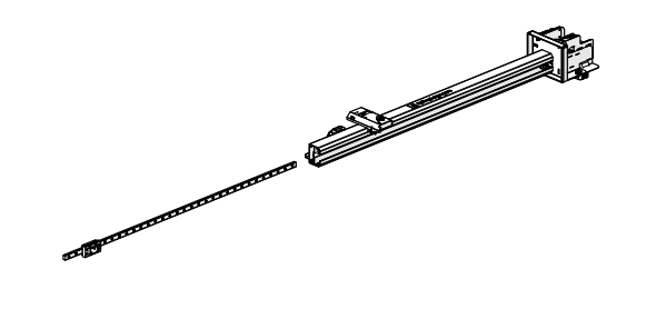
- Pull the x-axis belt away from the interior of the x-axis assembly to uncover the IKO rail.
- Loosen and remove the 3/32” Allen screws that secure the IKO rail bump stops on the left and right side of the IKO rail, taking note of their position for re-installation.
- Loosen and remove the remaining 3/32” Allen screws on the IKO rail.
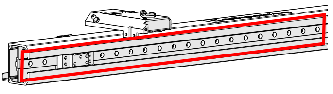 Note: There are unused screw holes in the IKO rail as the mounting screws are installed in every other opening.
 - After removing all of the IKO mounting screws, slide the IKO rail out through the left side of the x-axis assembly.
Linear Guide Installation
-
- Slide the IKO rail in through the left side of the x-axis assembly.
- Place the IKO rail bump stops into position at the left and right side of the IKO rail. Install and tighten the 3/32” Allen screws that secure them.
- Install and tighten the remaining 3/32” Allen screws on the IKO rail in every other screw opening.
- Place the end plate into position at the left side of the x-axis assembly. Install and tighten the four (4) Phillips screws that secure it.
- Place the x-axis belt back into the interior of the x-axis assembly. Place the x-axis belt clamps into position and install and tighten the four (4) 3/32” screws that secure them to the linear guide slider block.
- Ensure that the lower Delrin washer is in the correct position to allow the idler shaft to enter it and the opening on the idler body.
- Install the idler pulley.
- Install the upper Delrin washer and upper tensioner bracket.
- Install, but do not fully tighten the top four (4) 7/64” Allen screws on the x-axis idler assembly.
- Install the idler assembly front cover.
- Install and tighten the two (2) 7/64” Allen screws on the x-axis belt tensioner bracket to remove excess slack from the x-axis belt.
- Place the carriage assembly into position. Install and tighten the four (4) 3/32” Allen screws that secure it to the carriage assembly mounting plate.
- Place the autofocus switch into position. Install and tighten the 3/32” Allen screw that secures it to the carriage assembly.
- Slide the x-axis assembly into the cabinet through the right side of the engraver.
- Place the x-axis assembly on the y-axis bearing blocks ensuring that it sits on the locator pins.
- Install and tighten the four (4) fasteners that secure the x-axis assembly to the y-axis bearings. There are two (2) on the right side and two (2) on the left side.
- Slide the IKO rail in through the left side of the x-axis assembly.
Note: For Fusion Maker engravers, skip the remaining steps.
- Place the x-axis drive board and housing into position.
- Install and tighten the three (3) Phillips screws that secure the x-axis drive board mounting bracket to the x-axis assembly.
- Connect the six (6) electrical harnesses on the drive board.
Note: After replacing the IKO rail, complete the X‑Axis belt tensioning procedure. See the X‑Axis Belt Tensioning Guide (on the right) for details.
Was this helpful?
Thanks for your feedback!