In this lesson we’ll walk through replacing the Epilog Fusion M2’s CO2 Laser Tubes
Remove Panel
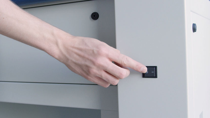
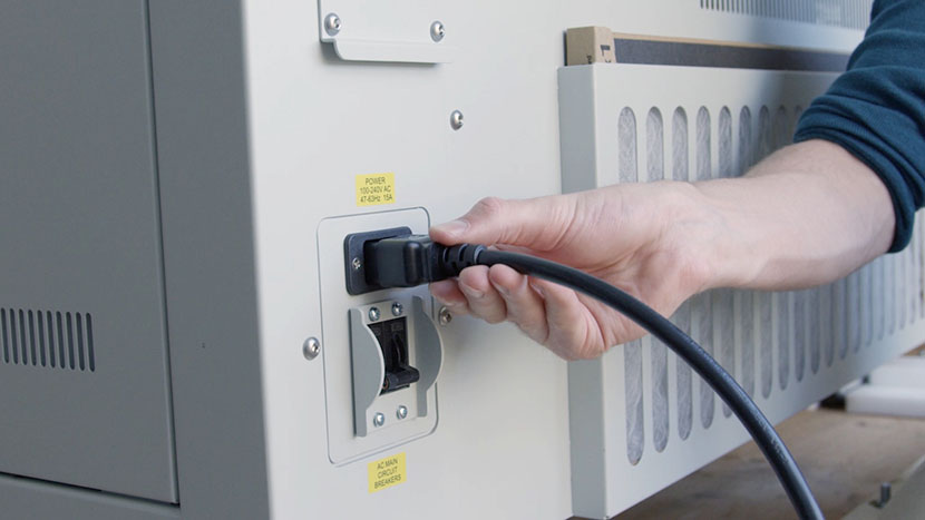
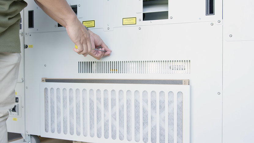
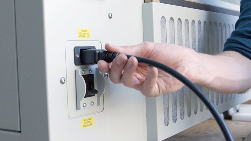
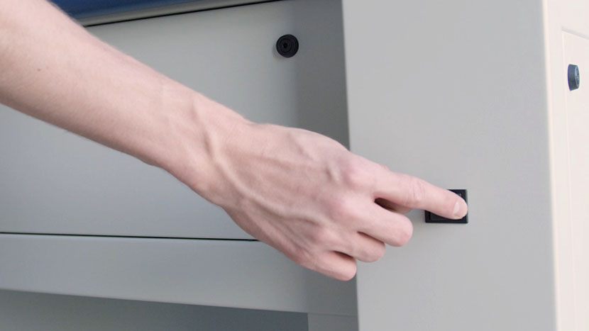
Shut off the laser and remove the power cord from the machine.
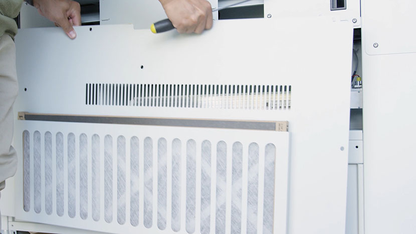
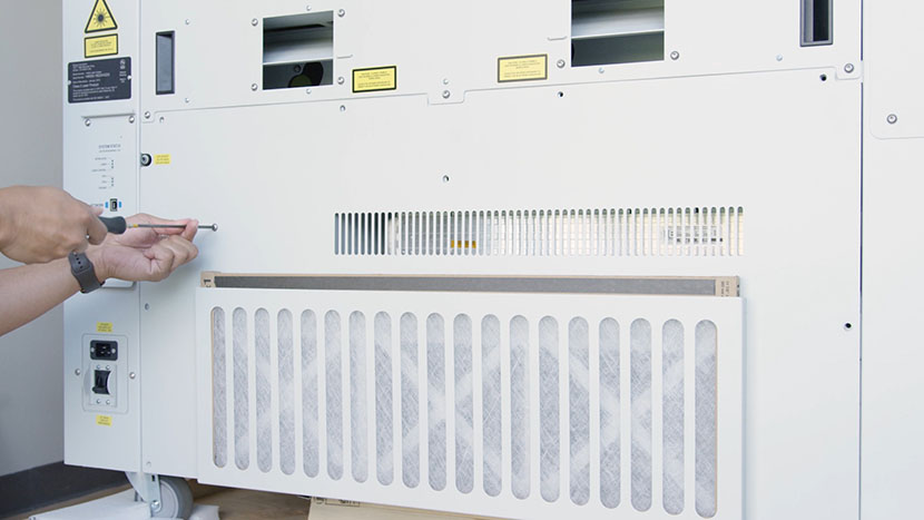
Use a 5/32” hex key to remove the ten hex screws which secure the lower panel on the rear of the machine, then remove the panel.
Remove Old Laser Tube
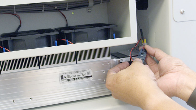
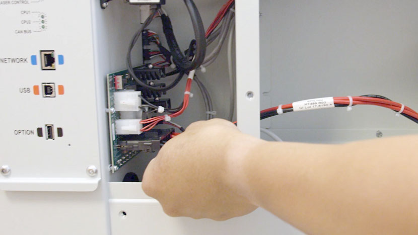
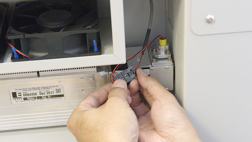
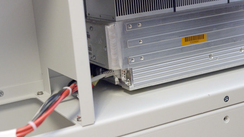
Disconnect the black connector from the right-hand side of the laser tube.
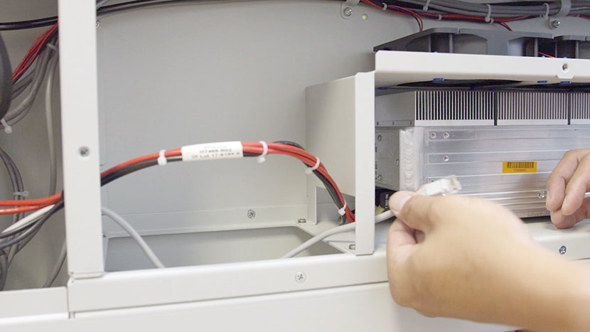
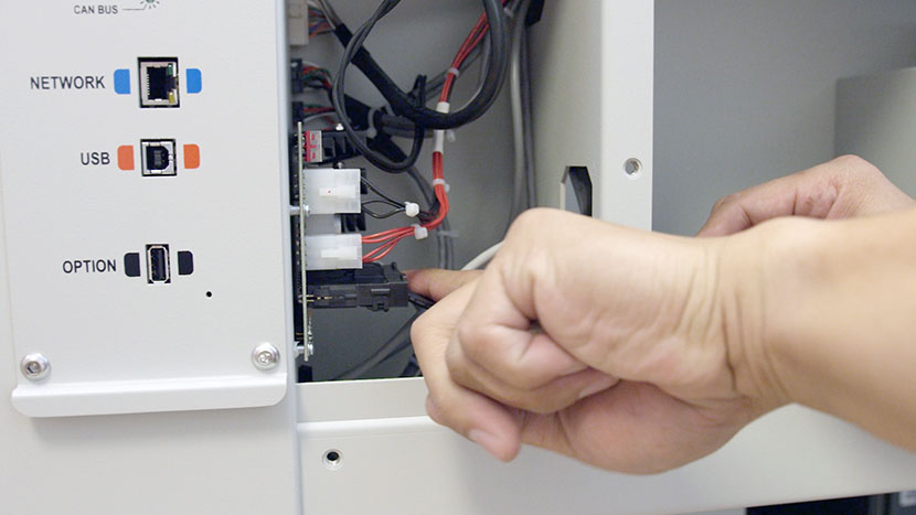
Remove the 8-Pin connector, which resembles an Ethernet or Telephone jack, from the left-hand side of the laser tube.
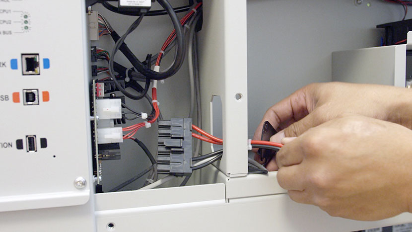
Disconnect the large black connector that connects the left-hand side of the laser tube to the circuit board in the left section of the rear compartment.
Use a 5/16” nut driver to remove the four nuts securing the U-shaped panel in the rear compartment’s central divider.
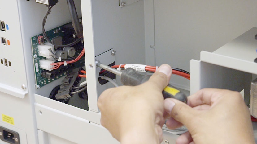
Set the panel aside and carefully pull the large black connector through the rubber flap in the central divider.
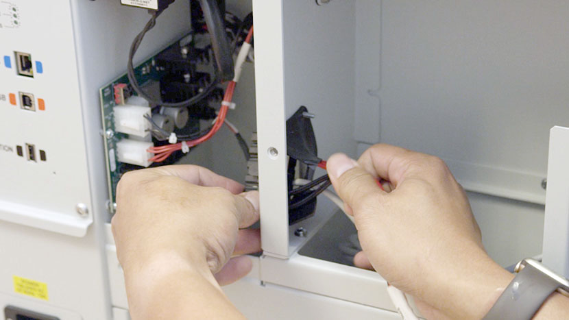
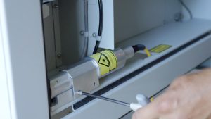
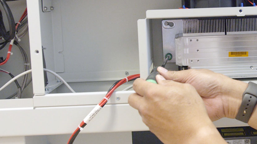
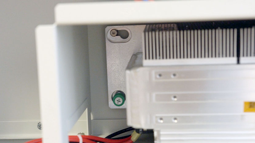
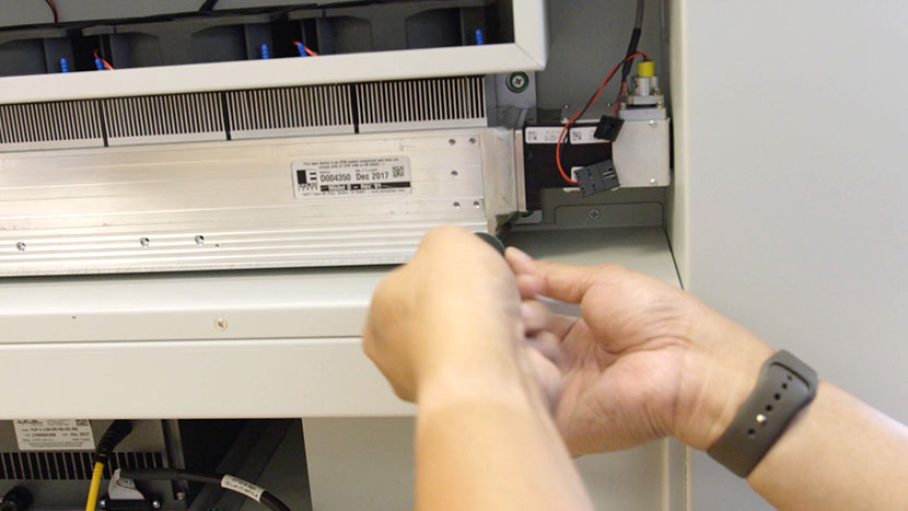
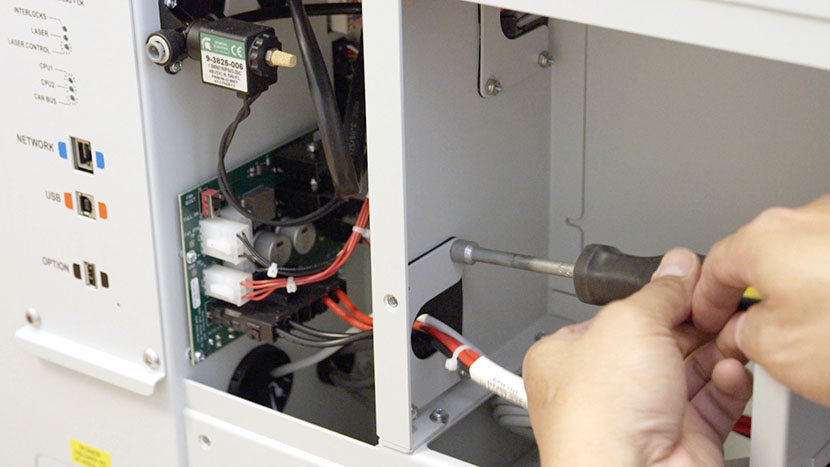
Use a Phillips head screwdriver to loosen the three green captive screws located in the right corners and the bottom left corner of the back of the laser tube.
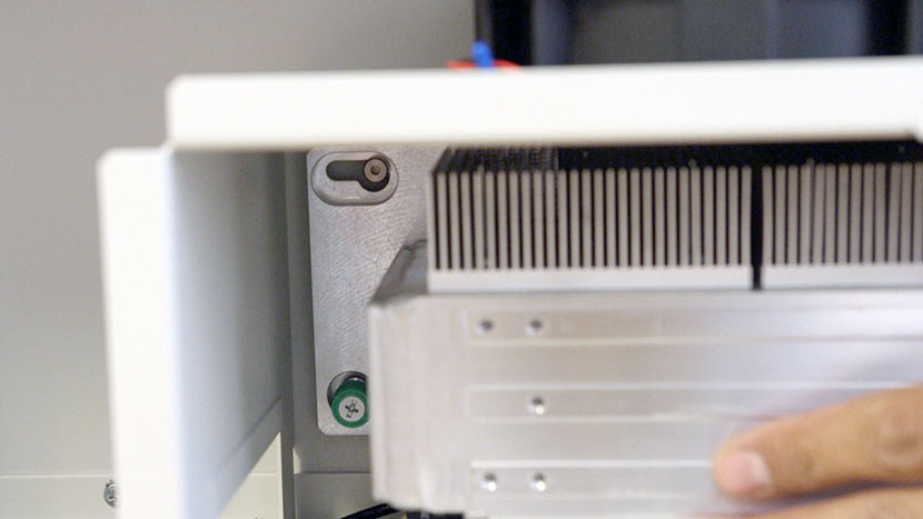
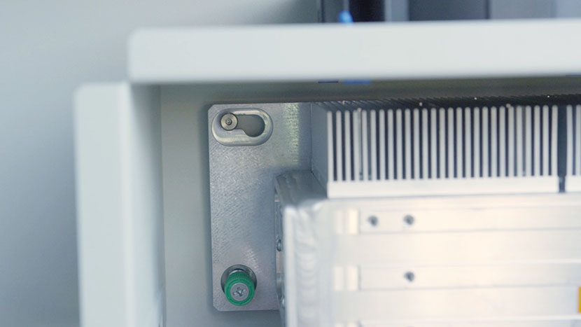
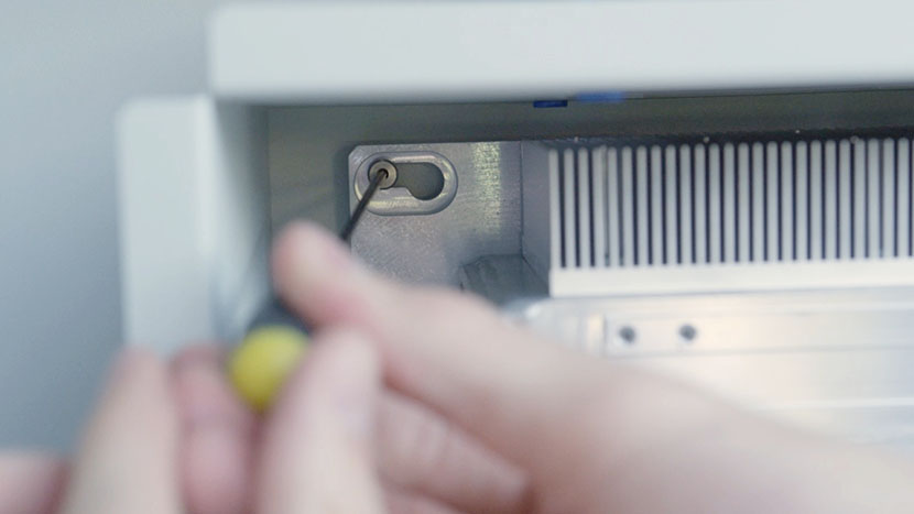
Use a 3/32” hex key to loosen the screw in the keyhole slot in the top left corner of the back of the laser tube.
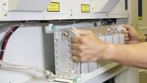
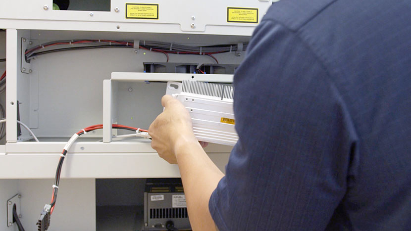
Slide the laser tube to the left so the top left screw clears the keyhole slot, then pull the tube out of the machine.
The assembly is quite heavy, so lift with caution.
Install New Laser Tube
Place the new laser tube in the machine, lining up the screw on the back of the machine with the open portion of the keyhole slot on the laser tube.
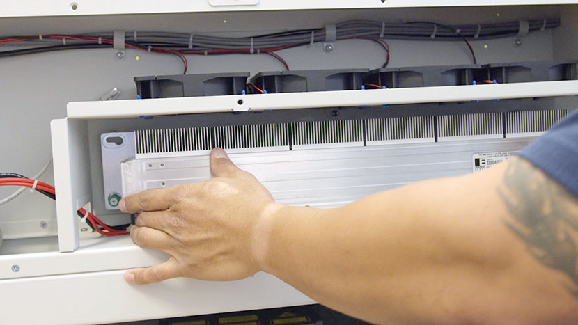
Make sure the laser tube is flush with the back of the compartment, then slide it to the right so the top left screw slides into the keyhole slot and the captive screws line up with the screw holes on the chassis.
Use a 3/32” hex key to tighten the top left screw and a Phillips head screwdriver to tighten the three captive screws.
Connect the black connector on the right-hand side of the laser tube.
Connect the 8-Pin connector to the left-hand side of the laser tube.
Feed the tube’s large black connector through the rubber flap in the central divider and plug it into the circuit board in the left section of the rear compartment.
Replace the U-shaped panel in the central divider by using a 5/16” nut driver to secure the four nuts. The open part of the ‘U’ should face the interior of the machine.
Reinstall Panel
Use a 5/32” hex key to insert the ten hex screws which secure the lower panel to the rear of the machine.
Plug the machine in and turn it on.
Before attempting to use the laser be sure to complete the laser alignment procedure.