In this lesson we’ll walk through replacing the Epilog Zing X-Axis Assembly.
Remove Right Side Panel
Shut off the laser and remove the power cord from the machine.

Inside the machine, move the x-axis assembly to the rear of the machine.

Put on the anti-static strap. Clip the strap on to any metal part of the machine. Always wear the anti-static strap when handling the control board to avoid damaging the unit through static discharge.

Loosen the two screws on the side of the display panel.

Grasp the two screws and pull the controller away from the engraver. A small amount of force will be required to remove the board from the machine as you disconnect the electrical connections.

Make sure the copper strips inside the control housing stay in place when you remove the board.

Next we’ll remove the right side panel from the machine.
Remove the three screws on the side of the machine.

Remove the screw on the back of the machine holding on the side panel.

Remove the right side cover by lifting up on the bottom of the cover and pulling toward you, then up.

Remove Left Side Panel
Remove the left side panel by removing the three screws on the side of the machine.

Remove the screw on the back of the machine.

Remove the left side panel by pulling it toward you.

Remove Old X-Axis Assembly
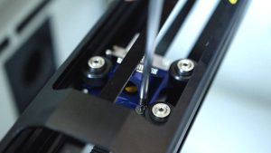
On the right side of the machine, using a standard length screwdriver, loosen the rear green captive screw. Move the X-axis assembly to the front of the machine and loosen the front green captive screw.


Move to the left side of the machine and loosen the two green captive screws.


Remove the Phillips head screw from the Air Assist tube.
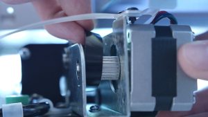
Remove the air assist tube. Start by removing the screw in the white nylon fastener which secures the air assist tube to the machine. Then press in on the white ring and pull the black tubing away (the nylon fastener will remain secured to the tube).


Remove the flex cable clamp by removing the two Phillips screws.

Remove the flex cable by pressing in on the cable lock and pulling the flex cable towards you.

Gently remove the x-axis assembly through the opening on the left side of the machine. Be mindful of the flex cable and air assist tube as you remove these items.

Install New X-Axis Assembly
Slide your new x-axis assembly in the left side of the machine.

Place the assembly back on its mounting points, aligning the green captive screws.

Starting on the left side, loosely install the two green captive screws.

Move to the right side and loosely install the front green captive screw. Move the rail to the rear of the machine and install the remaining green captive screw. Tighten all four screws, but make sure to not over-tighten them.


Reinstall the air assist tube in the black connector at the right rear of the machine.

Install the screw in the white nylon fastener which retains the air assist tube.

Install the white ribbon cable.

Install the small clamp over the top of the white ribbon cable.

Reattach Left Side Panel
Reinstall the left side panel by reattaching the three screws on the side of the machine.

Tighten the screw on the back of the machine.

Reattach Right Side Panel
Replace the right side panel, tightening the three screws on the side of the panel.


Tighten the screw on the back of the machine.

Slide the display unit into place, ensuring the tabs on the control unit fit into the grooves on the side of the housing. Push the display unit all the way into the slots until it is fully seated. Tighten the two screws to secure the display unit in place.


Plug the machine in and turn it on.

Perform an optical alignment to ensure the optimal operation of the laser.