In this lesson we’ll walk through replacing the Epilog Zing X-Motor.
Remove Right Side Panel
Shut off the laser and remove the power cord from the machine.

Inside the machine, move the x-axis assembly to the rear of the machine.

Put on the anti-static strap. Clip the strap on to any metal part of the machine. Always wear the anti-static strap when handling the control board to avoid damaging the unit through static discharge.

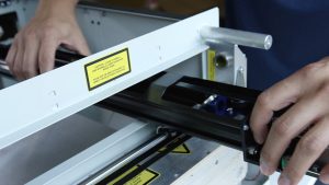
Loosen the two screws on the side of the display panel.

Grasp the two screws and pull the controller away from the engraver. A small amount of force will be required to remove the board from the machine as you disconnect the electrical connections.

Make sure the copper strips inside the control housing stay in place when you remove the board.

Next we’ll remove the right side panel from the machine.
Remove the three screws on the side of the machine.

Remove the screw on the back of the machine holding on the side panel.

Remove the right side cover by lifting up on the bottom of the cover and pulling toward you, then up.

Remove Left Side Panel
Remove the left side panel by removing the three screws on the side of the machine.

Remove the screw on the back of the machine.

Remove the left side panel by pulling it toward you.

Remove Old Motor
On the belt assembly on the left side of the machine, loosen the two Phillips screws on the metal plate.


Push the idler bracket back toward the inside of the assembly to loosen the belt tension. Once moved, tighten the Phillips screws a little to hold the idler mount in place.

Push the x-axis assembly to the front of the machine.

Remove the two Phillips screws on the metal plate on the side of the x-axis motor.


Push the x-axis assembly to the back of the machine.

Unclip the flex cable.

Disconnect the electrical connection behind the motor and set the old motor aside.

Install New Motor
To install the new motor, reconnect the motor’s electrical connection and plug in the flex cable.


Push the x-axis assembly to the front of the machine.
As you place the new motor in the opening in the x-axis, loop the belt over the x-motor pulley.

Install the two mounting screws on the side of the motor.


On the left side of the machine, loosen the two idler bracket screws and let the springs apply the tension to the x-axis belt. Ensure the idler bracket is square in the machine, then tighten the two screws again.


Reattach Left Side Panel
Reinstall the left side panel by sliding it onto the chassis and reattaching the three screws on the side of the machine.

Tighten the screw on the back of the machine.

Reattach Right Side Panel
Replace the right side panel, tightening the three screws on the side of the panel.


Tighten the screw on the back of the machine.

Slide the display unit into place, ensuring the tabs on the control unit fit into the grooves on the side of the housing. Push the display unit all the way into the slots until it is fully seated. Tighten the two screws to secure the display unit in place.


Plug the machine in and turn it on.