In this lesson we’ll walk through replacing the Epilog Fusion M2’s x-axis assembly.
Remove Panels
With the machine powered on, use the control panel to scroll down to ‘Jog.’
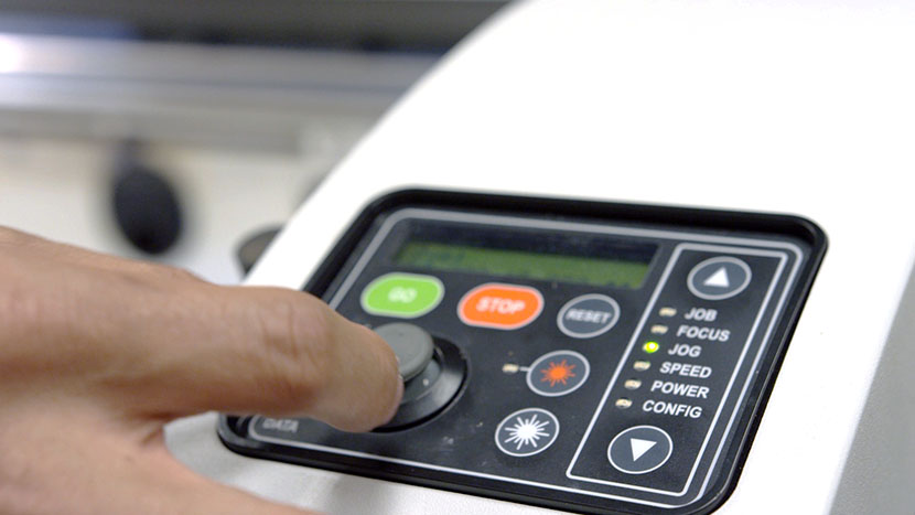
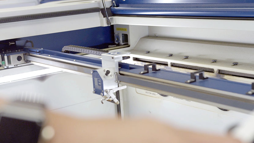
Then use the joystick to move the x-axis assembly toward the middle of the machine to give you room to work.
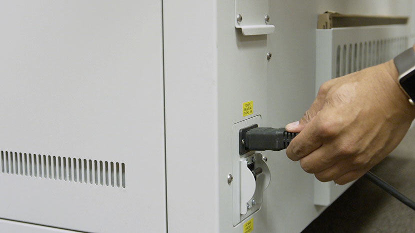
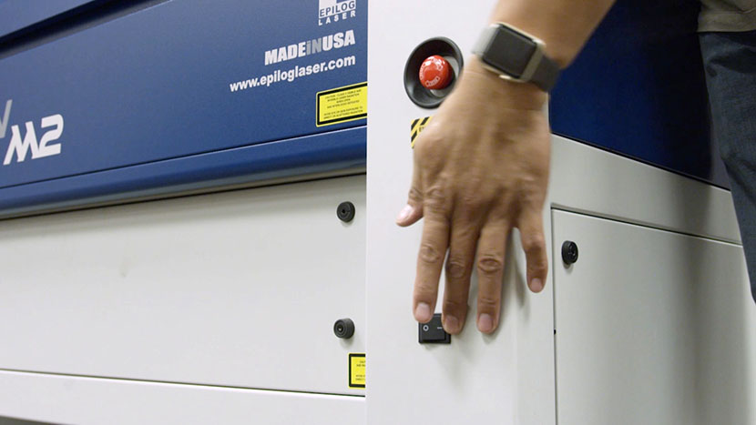
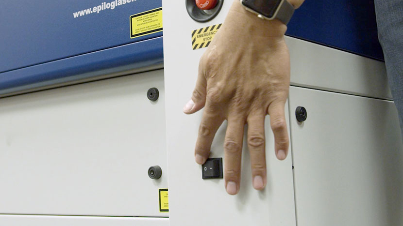
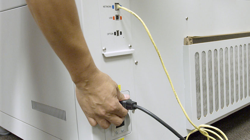
Shut off the laser and remove the power cord from the machine.
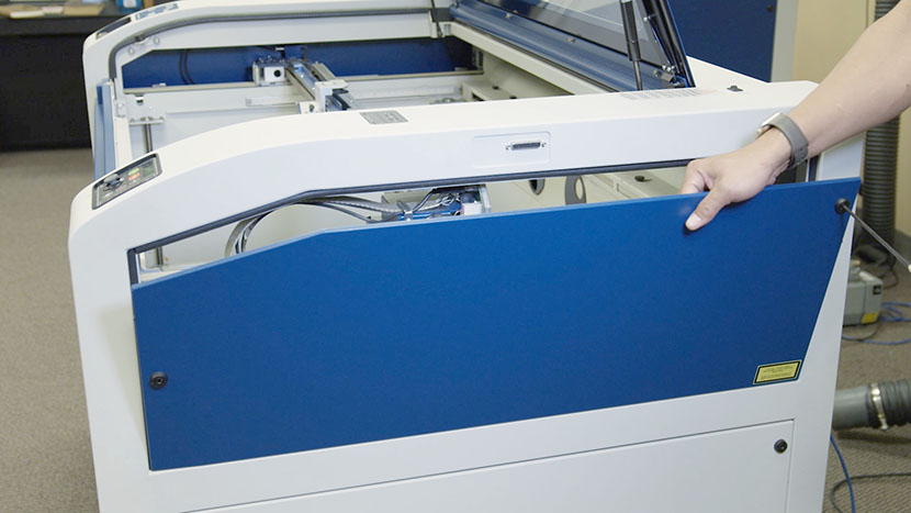
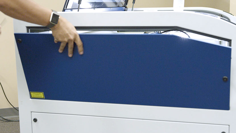
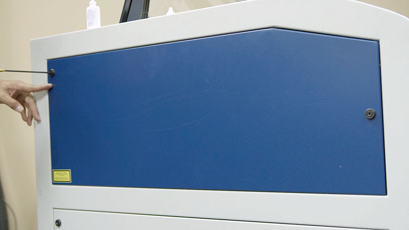
Remove the top access panels on both the left and right side of the machine by using a 5/32” hex key to turn the black panel locks ¾ of the way counter-clockwise.
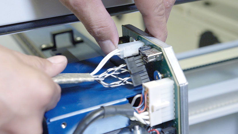
Disconnect X-Axis Assembly
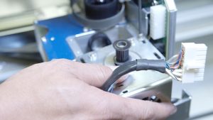
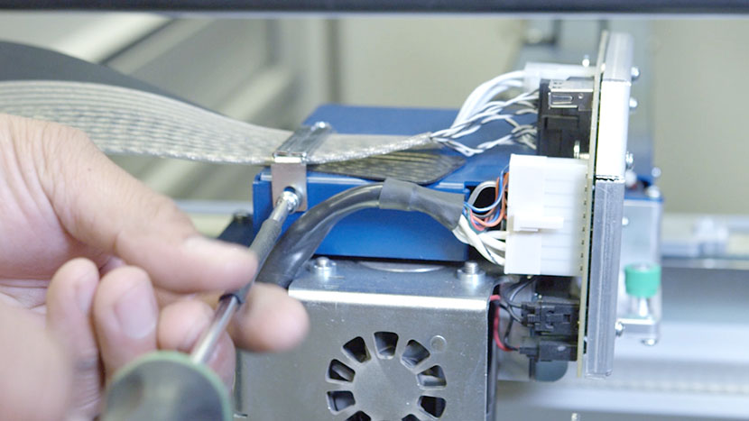
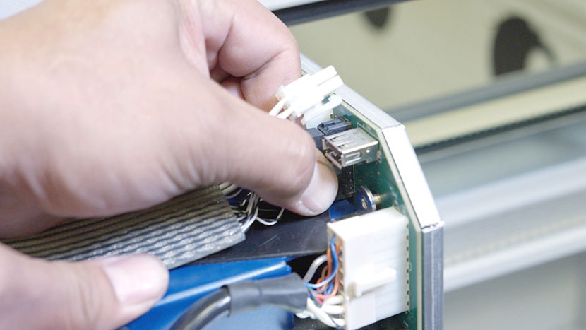
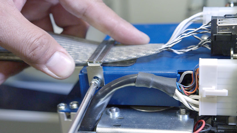
On the right side of the machine, locate the wire harness, which electronically connects the x-axis assembly to the rest of the system. The wire harness and its plastic guard are held secure by the wire harness clamp. With a screwdriver, remove the clamp screw on the side of the blue housing and loosen the clamp screw on top. Then remove the clamp and set it aside.
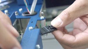
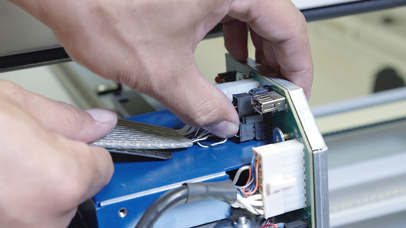
Next, disconnect the white connector from its socket by squeezing the lock tab on the bottom of the connector and pulling it away from the circuit board.
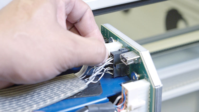
Remove the black connector as well.
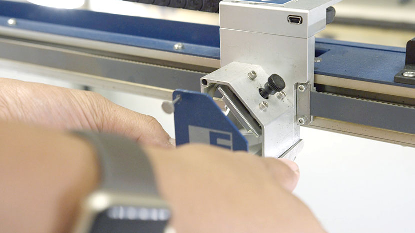
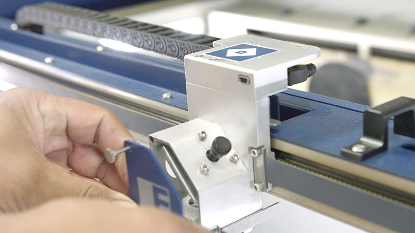
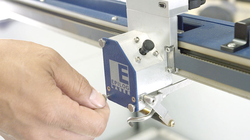
Now, remove the lens assembly by loosening the three thumb screws on its front face until they spin freely. They are captive screws and will not come out of the assembly.
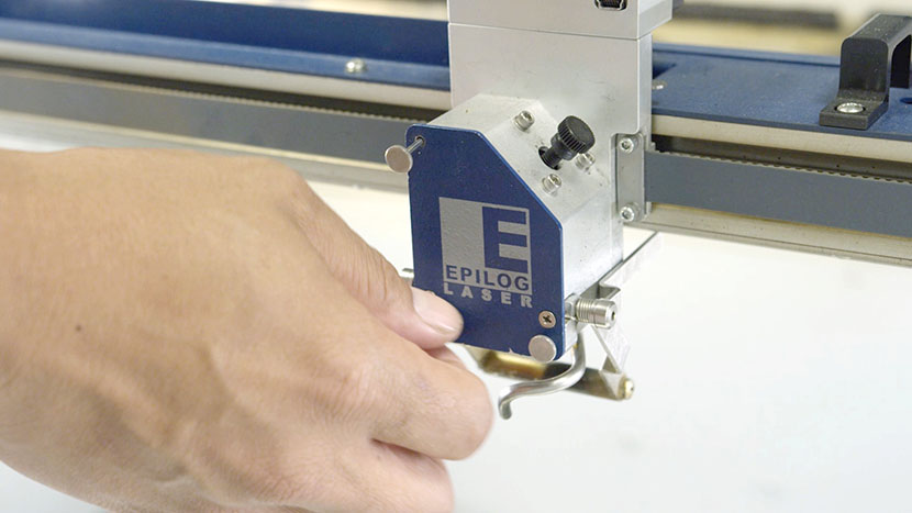
Slide the assembly out of its housing and set it aside.
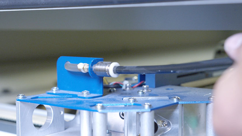
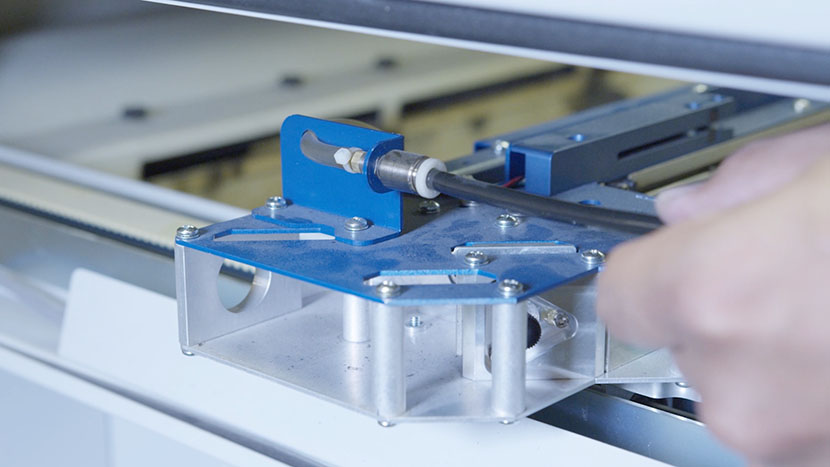
On the left side of the machine, find and disconnect the Air Assist tube from the x-axis assembly. Press the ring toward the rear of the engraver while pulling on the black tube.
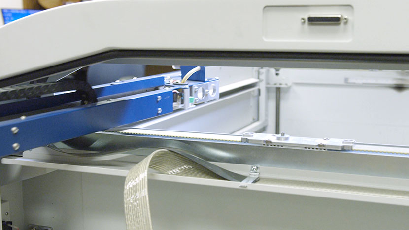
Remove Old X-Axis Assembly
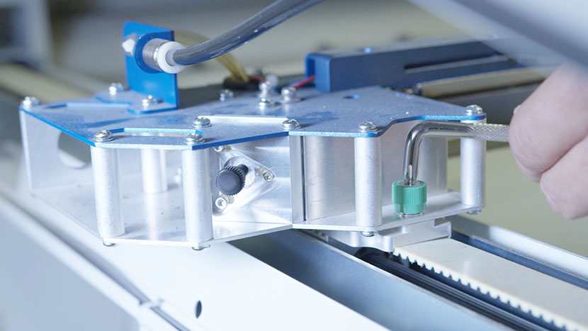
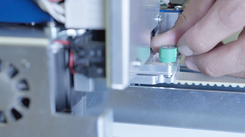
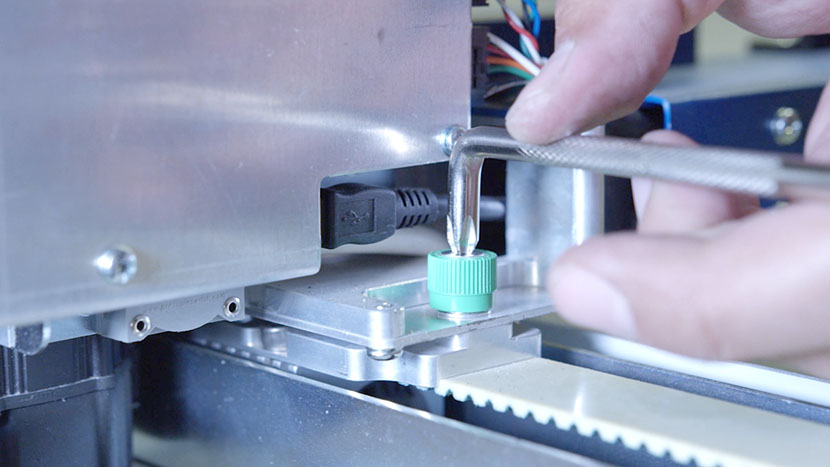
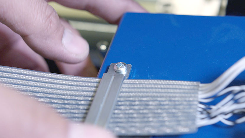
Now it’s time to remove the x-axis assembly. On both ends of the assembly, loosen the two green captive screws until they turn freely.
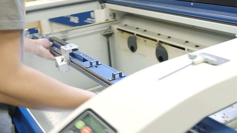
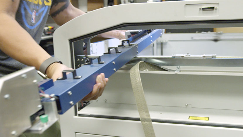
Carefully lift the assembly from its mounted position and carry it out through the right side of the machine.
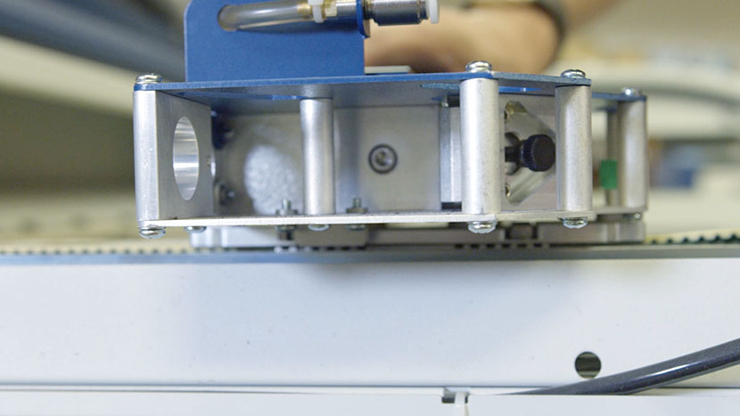
Install New X-Axis Assembly
Insert the new x-axis assembly through the right side of the machine. Place it on its mounting points, lining it up with the guide pins so there is no space between the bottom of the assembly and the screw mounts.
Use a screwdriver to tighten the green captive screws on both sides.
Next, connect the wire harness by plugging in the black and white connectors.
Retrieve the wire harness clamp and position the wire harness and its plastic guard so that the harness is on top of the guard and both are under the clamp on the x-axis assembly. Be sure that the wires between the wire harness and the circuit board have some slack and are not drawn tight.
Secure the clamp by inserting the two screws with a screwdriver.
Reinsert the Air Assist tube on the left end of the assembly. The ring will pop out once the tube is fully inserted.
Reinstall the lens assembly by sliding it into its housing and tightening the three screws on its front face.
Reinstall Panels
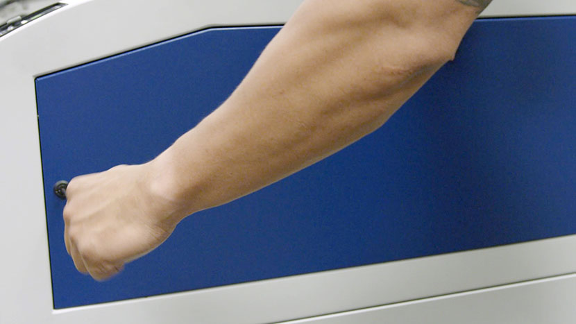
Replace the top access panels on the left and right sides of the machine, using a 5/32” hex key to turn the black panel locks ¾ of the way clockwise.
Plug the machine in and turn it on.