In this lesson we’ll walk through replacing the Epilog Fusion M2’s X-Axis Sensors.
Depending on your needs, you may only need to replace one of these sensors.
Remove Panels
We’ll start by replacing the left sensor, then move on to the right sensor.
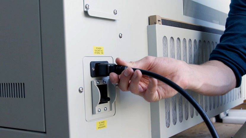
Shut off the laser and remove the power cord from the machine.

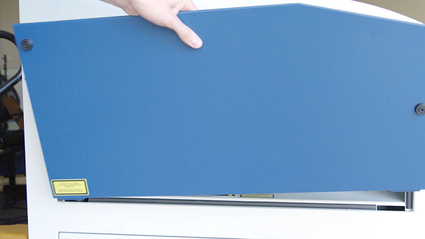
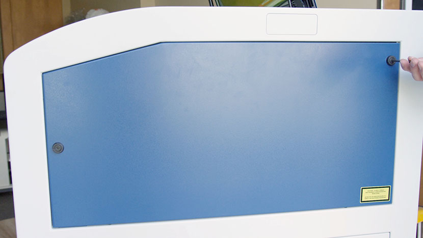
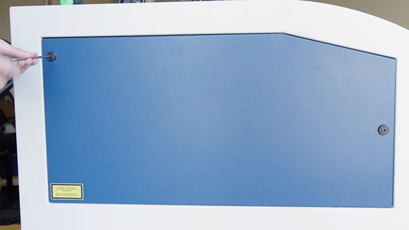
Remove the top access panels on both the left and right side of the machine by using a 5/32” hex key to turn the black panel locks ¾ of the way counter-clockwise.

Shift X-Axis Assembly Right
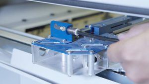
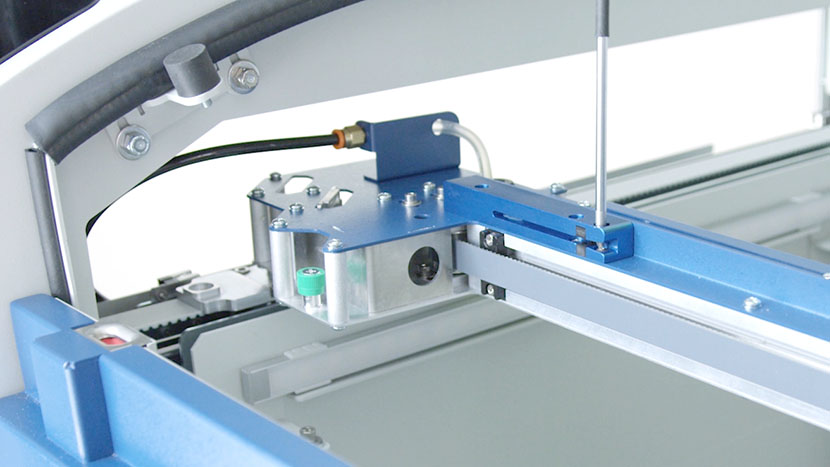
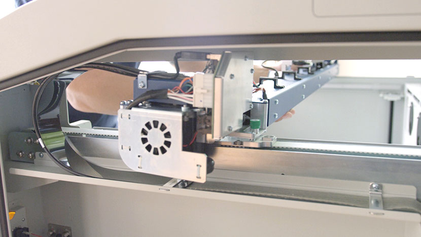
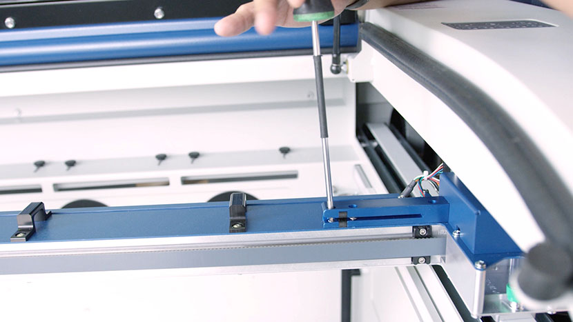
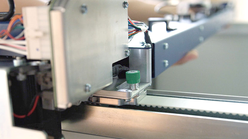
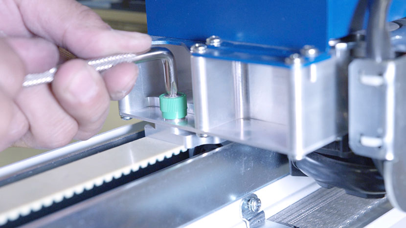
On both ends of the x-axis assembly, loosen the two green captive screws until they turn freely.
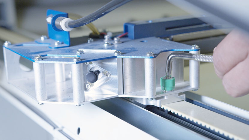
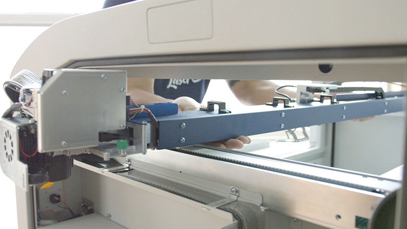
Carefully lift the assembly from its mounted position and shift it to the right, allowing the left end of the assembly to rest on the left side of the chassis so that all three screws on the left sensor housing are easily accessible.
Remove Old Left Sensor
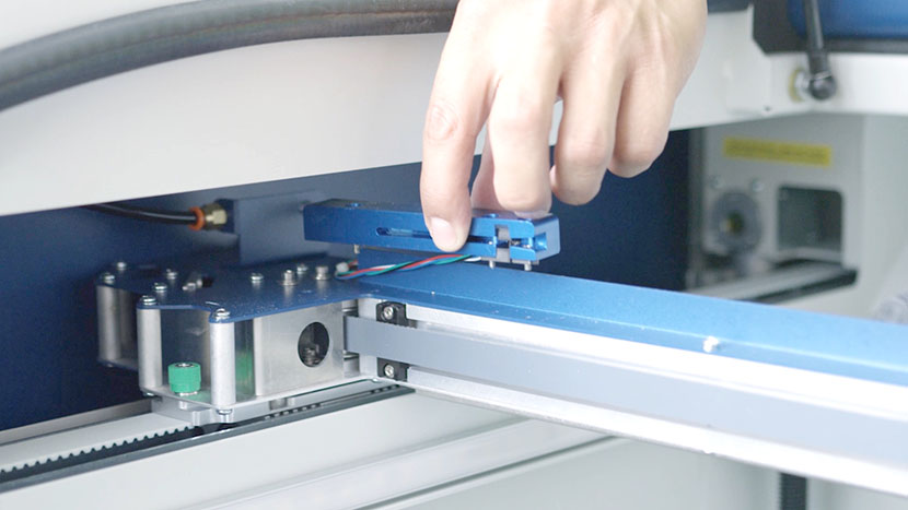
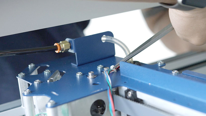
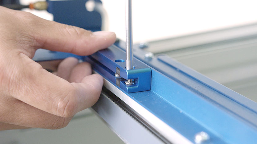
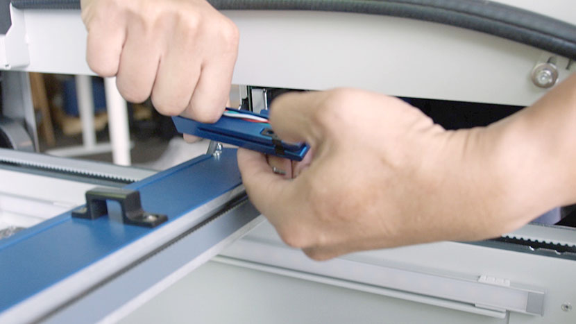
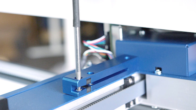
Use a Phillips-head screwdriver to loosen the three screws securing the sensor housing.
Upend the sensor housing and catch the screws as they fall free.
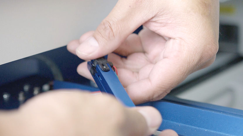
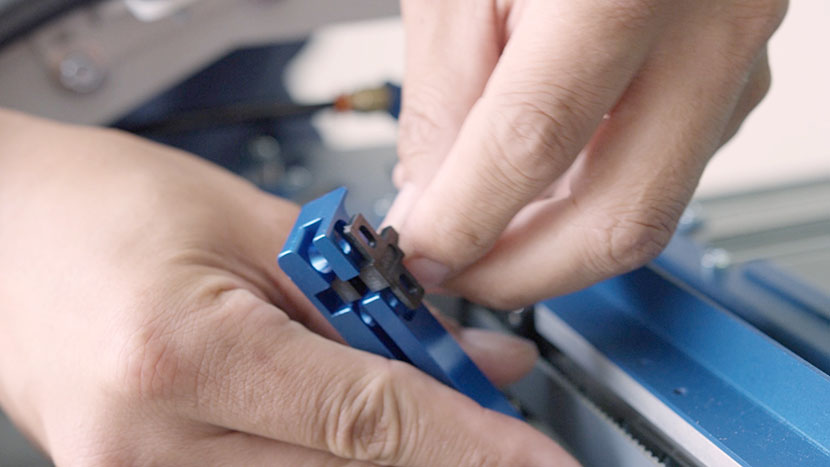
Slide the sensor down out of the housing and set the housing aside.
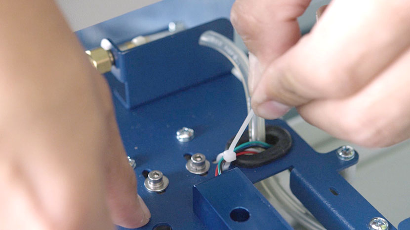
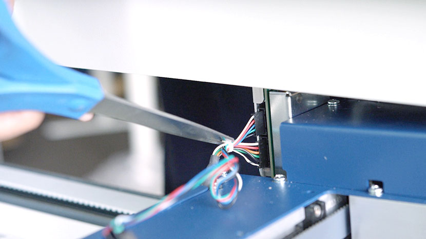
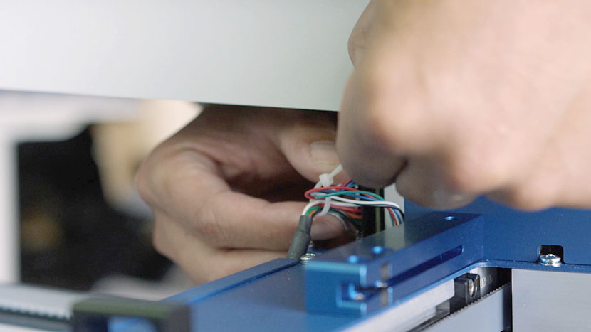
Cut the zip tie securing the sensor wires to the x-axis assembly.
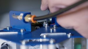
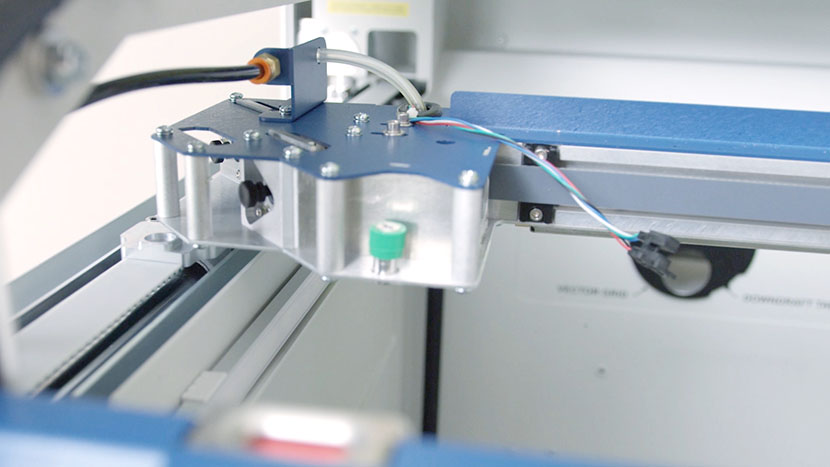
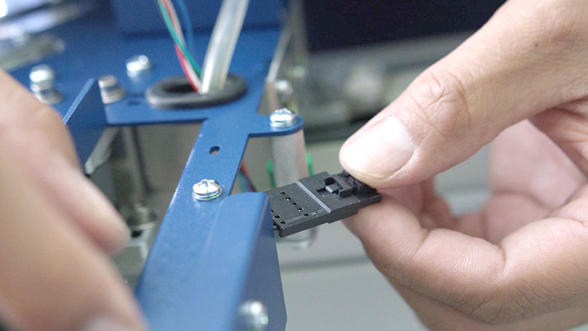
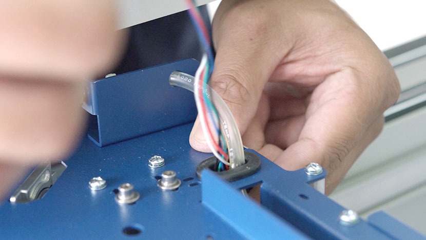
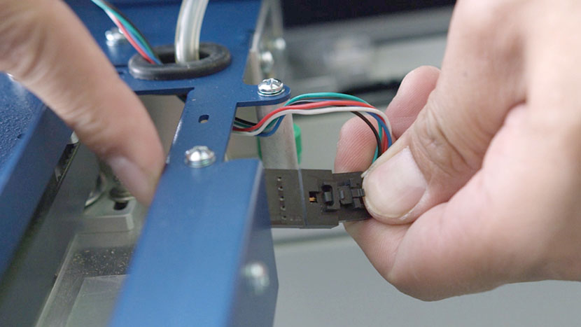
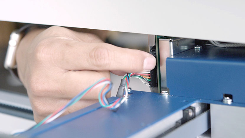
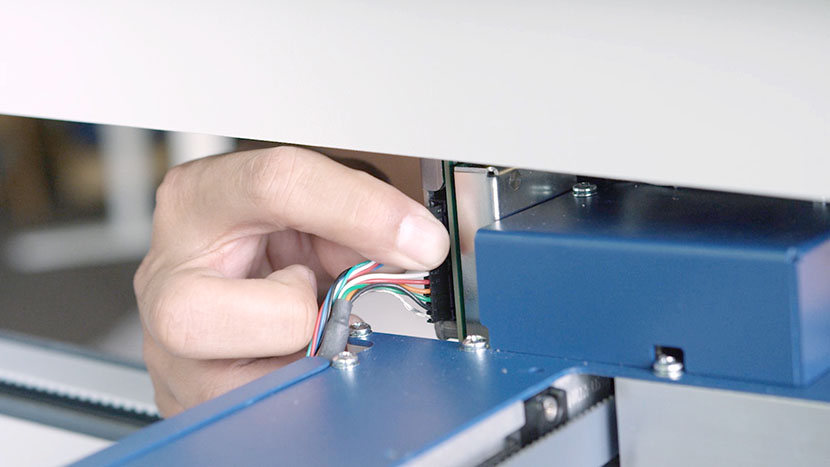
In the back of the x-axis assembly, disconnect the sensor’s black connector and slide it out through the hole where the Air Assist tube is also located.
Set the old sensor aside.
Install New Left Sensor
Take the new sensor and insert the black connector through the hole with the Air Assist tube.
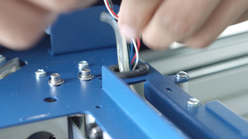
Reconnect it with the black connector in the back of the x-axis assembly.
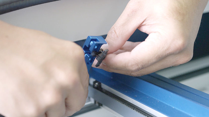
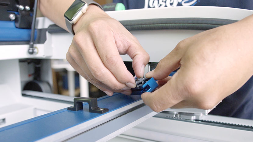
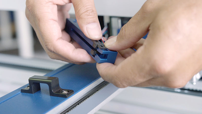
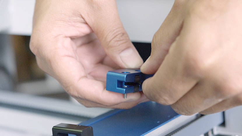
Slide the sensor into the slot on the sensor housing.
Hold the sensor housing upright, supporting the senor so that it doesn’t fall out, and insert the two screws that secure the sensor.
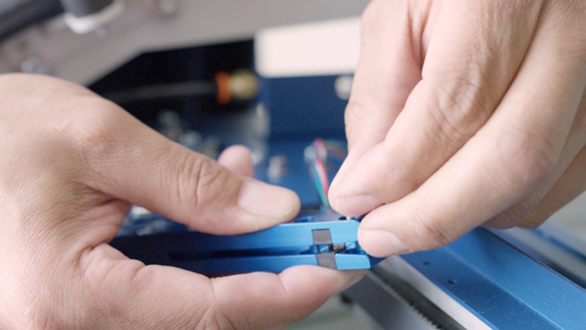
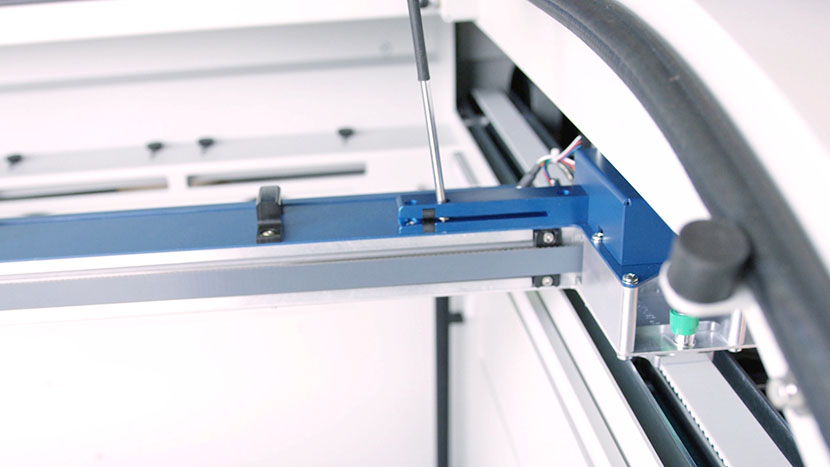
Align the sensor housing with the screw holes on the x-axis assembly and screw in the two screws.
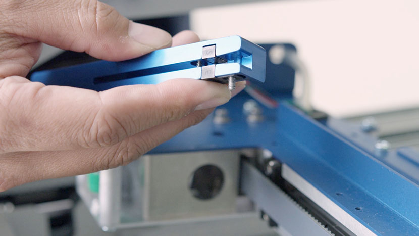
Then screw in the third screw on the left end of the sensor housing.
Slide a new zip tie through the two small slots on the x-axis assembly and secure it around the sensor’s wires.
Cut off any excess length of the zip tie.
Shift X-Axis Assembly Left
Now shift the x-axis assembly to the left, allowing the right end of the assembly to rest on the right side of the chassis so that all three screws on the right sensor housing are easily accessible.
Remove Old Right Sensor
Use a Phillips head screwdriver to loosen the three screws securing the sensor housing.
Upend the sensor housing and catch the screws as they fall free.
Slide the sensor down out of the housing and set the housing aside.
Cut the zip tie securing the sensor’s wires to the other set of wires.
Disconnect the sensor’s black connector and set the sensor aside.
Install New Right Sensor
Connect the new sensor’s black connector.
Slide the sensor into the slot on the sensor housing.
Hold the sensor housing upright, supporting the senor so that it doesn’t fall out, and insert the two screws that secure the sensor.
Align the sensor housing with the screw holes on the x-axis assembly and screw in the two screws.
Then screw in the third screw on the right end of the sensor housing.
Secure the sensor’s wires to the other set of wires with a new zip tie. Cut off any excess length of the zip tie.
Reinstall X-Axis Assembly
Place the x-axis assembly back on its mountings and secure it by tightening its four green captive screws.
Reinstall Panels
Replace the top access panels on the left and right sides of the machine, using a 5/32” hex key to turn the black panel locks ¾ of the way clockwise.
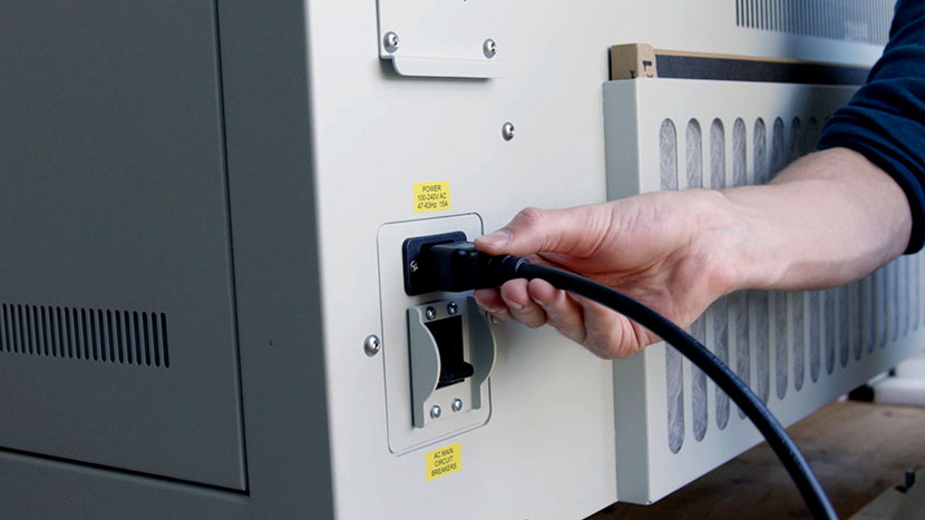
Plug the machine in and turn it on.