In this lesson we’ll walk through replacing the Epilog Fusion M2’s X-motor.
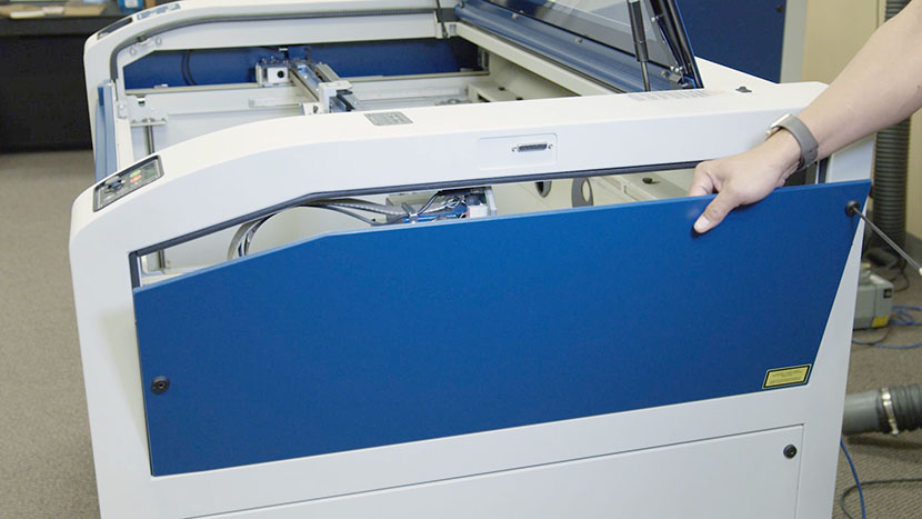
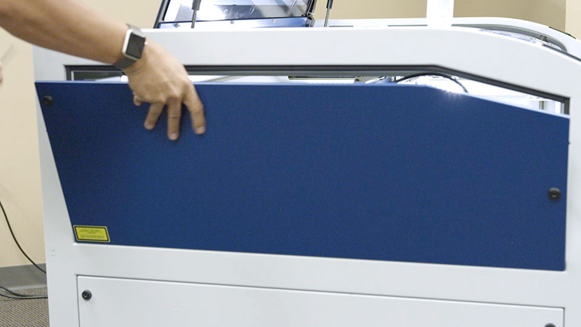
Remove Side Panels
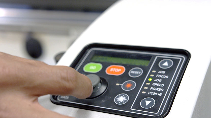
With the machine powered on, use the control panel to scroll down to ‘Jog.’
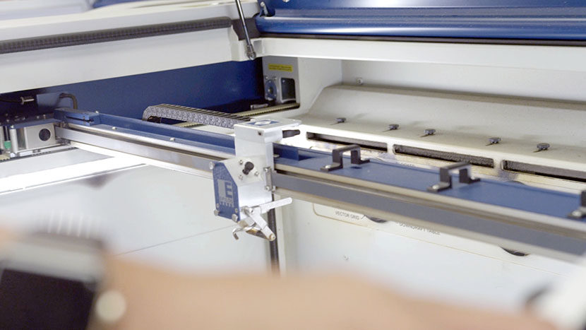
Then use the joystick to move the x-axis assembly toward the middle of the machine to give you room to work.
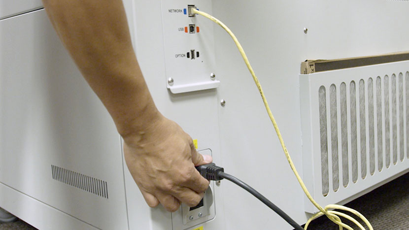
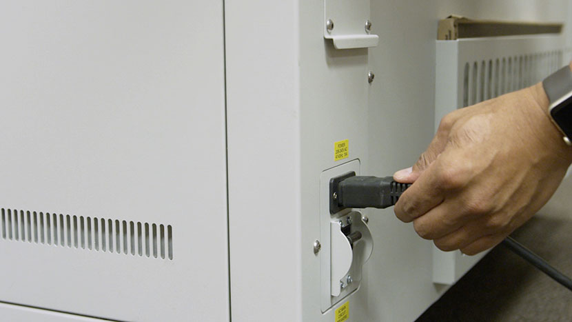
Shut off the laser and remove the power cord from the machine.

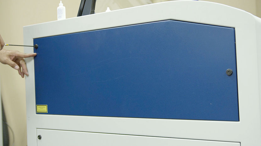
Remove the top access panels on both sides of the machine by using a 5/32” hex key to turn the black panel locks ¾ of the way counter-clockwise.
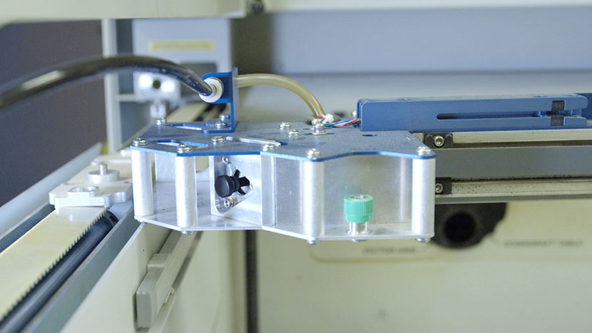
Disconnect X-Axis Assembly
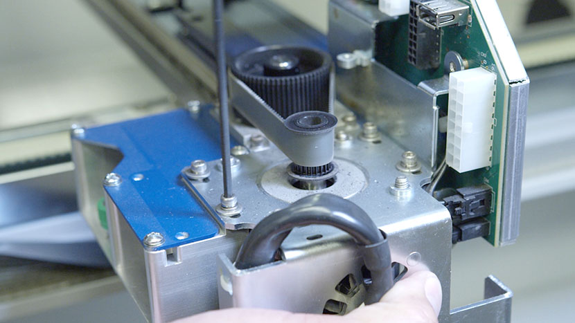
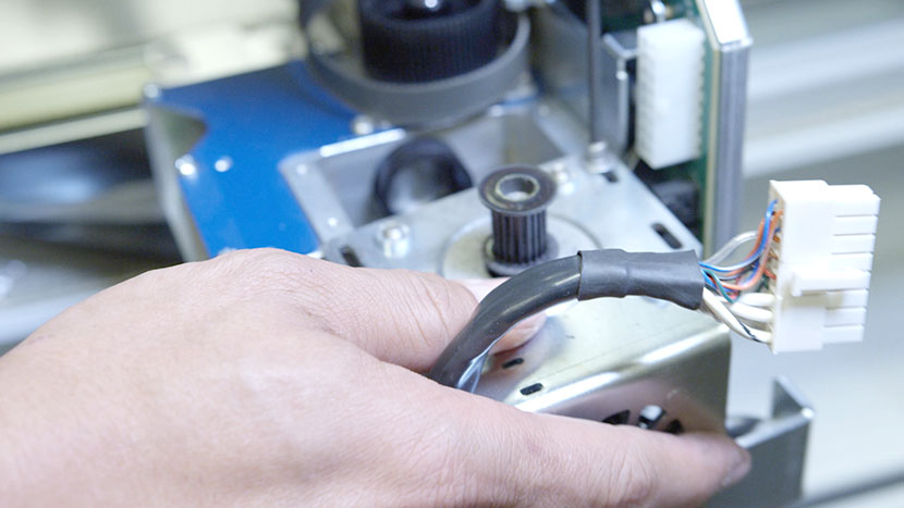
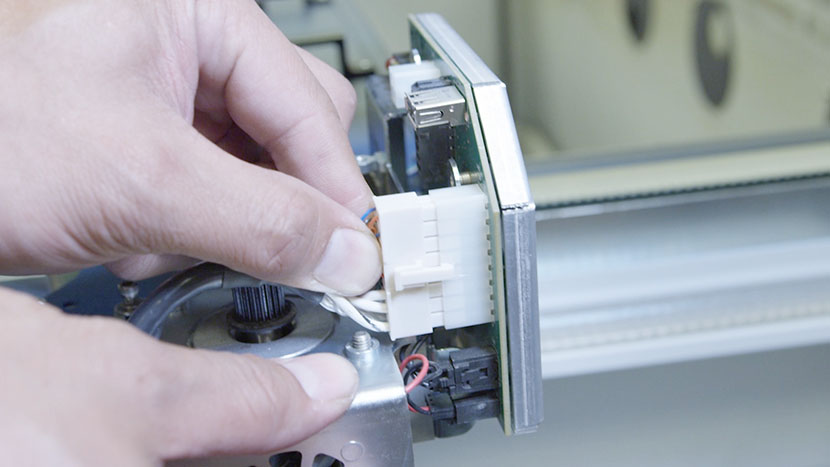
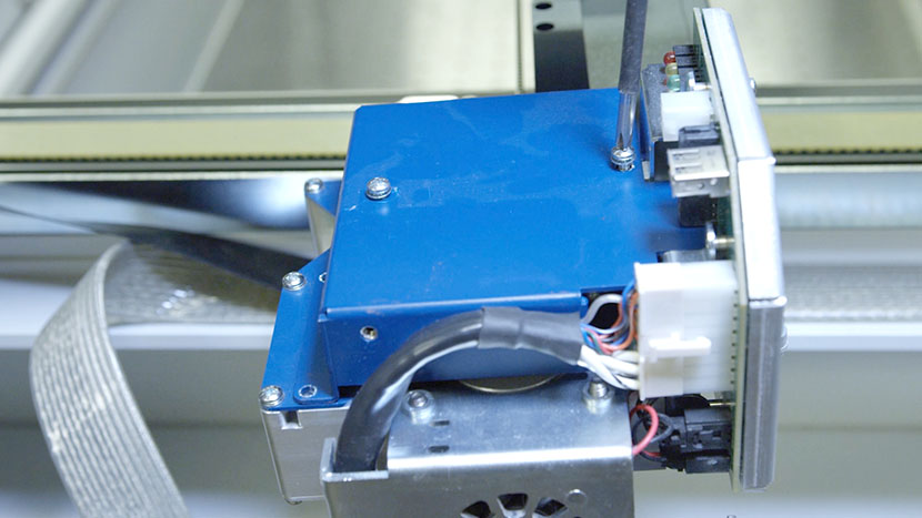
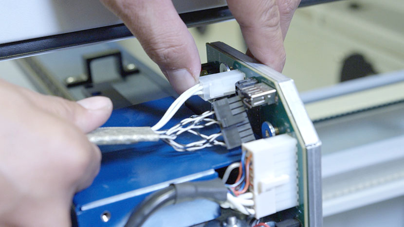
On the right side of the machine, locate the wire harness, which electronically connects the x-axis assembly to the rest of the system.
The wire harness and its plastic guard are held secure by the wire harness clamp.
With a screwdriver, remove the clamp screw on the side of the blue housing and loosen the clamp screw on top. Then remove the clamp and set it aside.
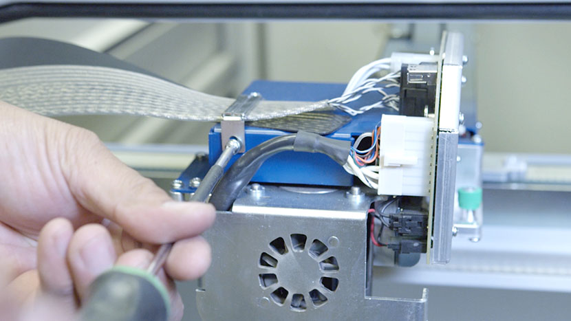
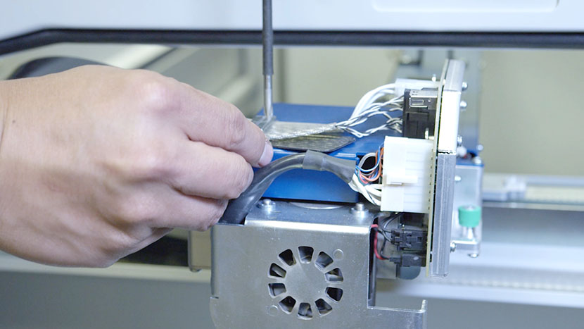
Next, disconnect the white connector from its socket by squeezing the lock tab on the bottom of the connector and pulling it away from the circuit board.
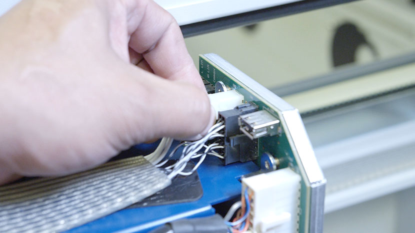
Remove the black connector as well.
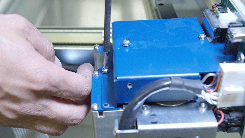
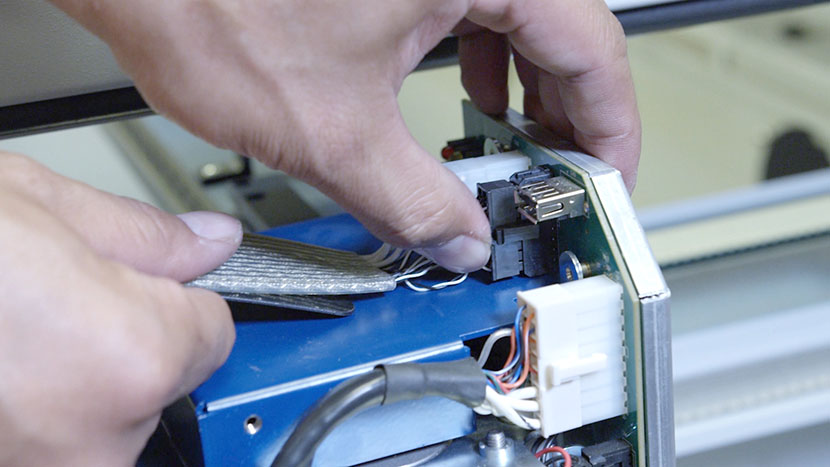
Move the wire harness and its plastic guard to the side.
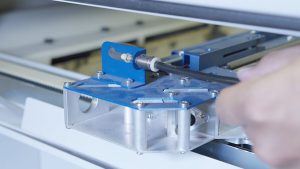
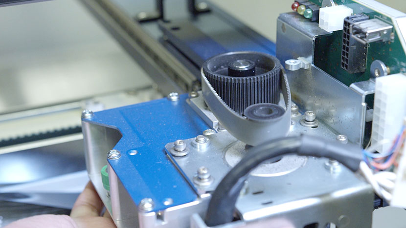
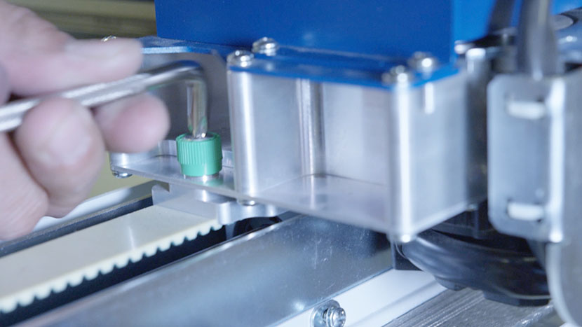
On both ends of the assembly, loosen the two green captive screws until they turn freely.
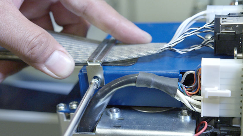
Carefully lift the assembly from its mounting position and shift it to the right, allowing the left end of the assembly to rest on the left side of the chassis.
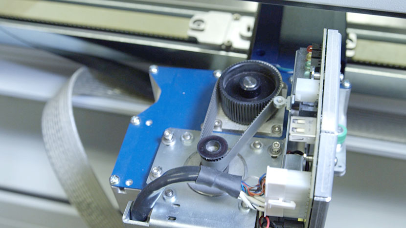
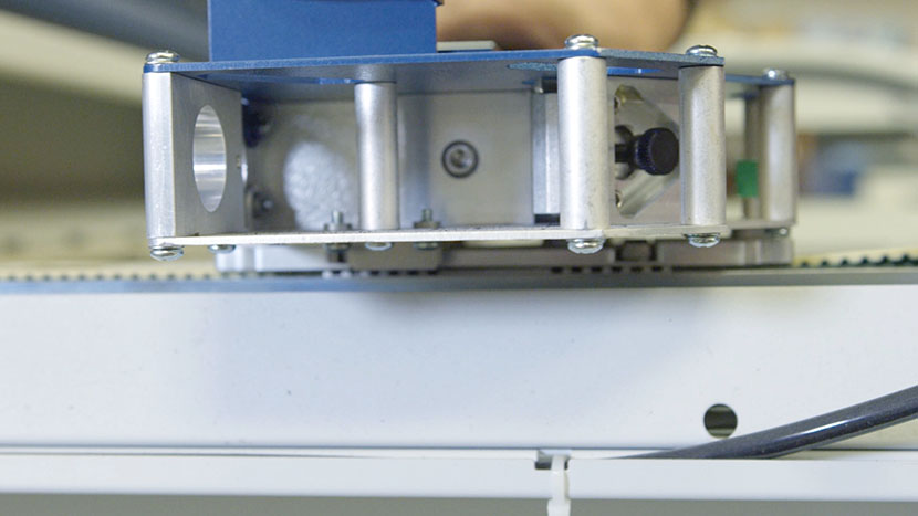
Gain Access to the X-Motor
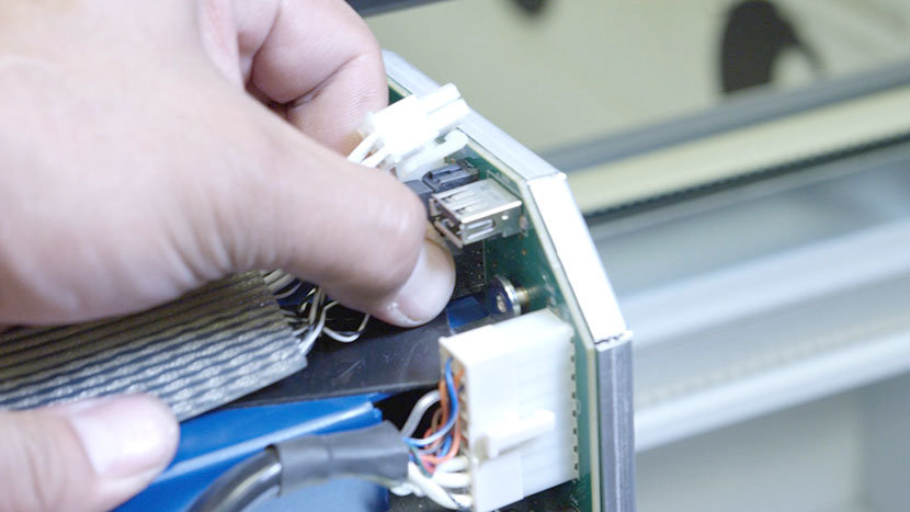
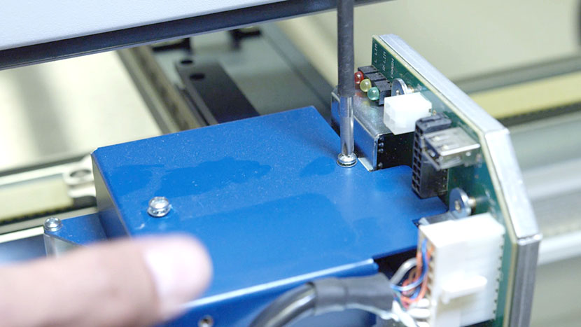
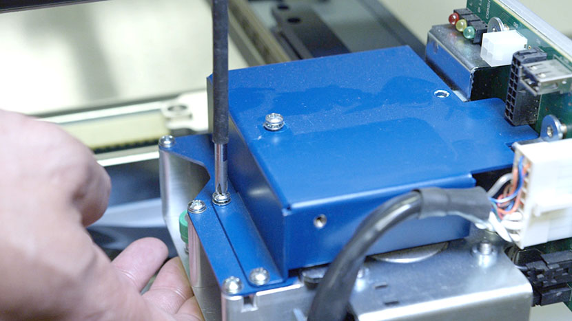
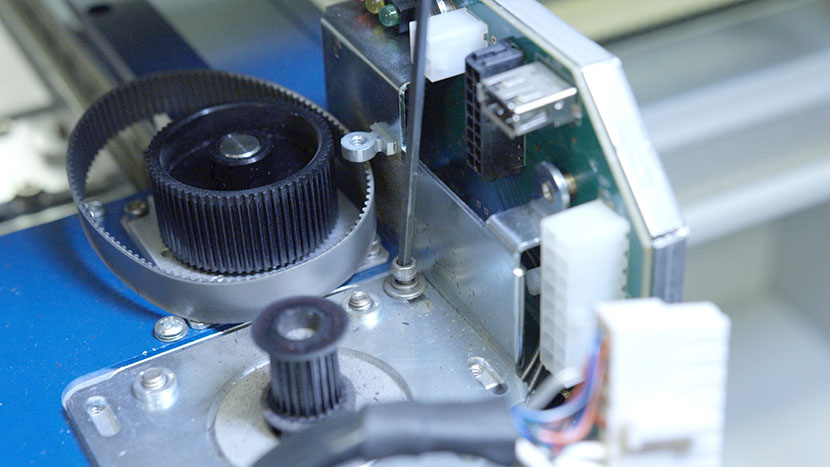
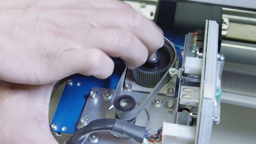
Remove the blue cable guard by unscrewing the top Phillips head screw near the rear of the guard and the two Phillips head screws at the front bottom edge of the guard.
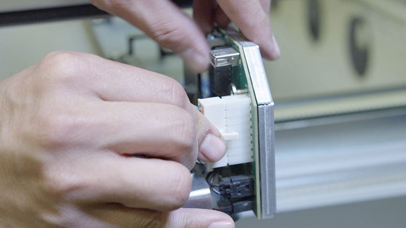
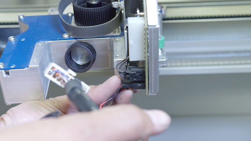
Disconnect the large white connector by squeezing the lock tab on the side of the connector and pulling it away from the circuit board.
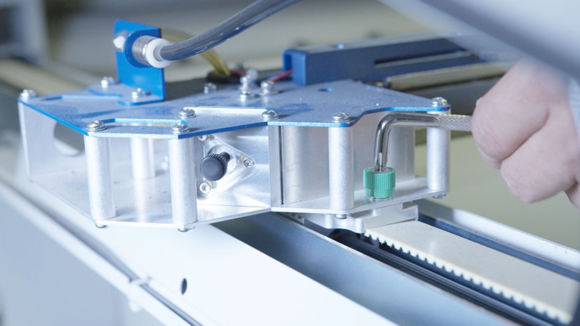
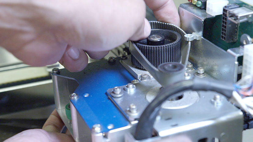
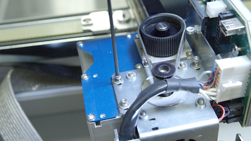
Using a 7/64” hex key, loosen, but do not remove, the four motor mounting screws.
Press the motor in toward the center of the machine, loosening the reducer drive belt.
Remove the belt.
Remove the Old Motor
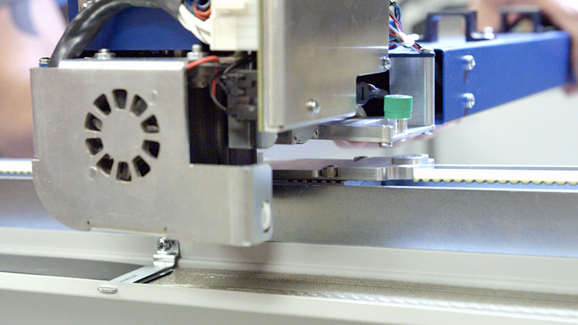
Now it’s time to remove the x-motor. Remove the four motor mounting screws. The x-motor may move away from the machine slightly as the internal tensioning spring pushes it outward.
Hold the x-motor away from the x-axis assembly so you can see the black connector attaching the x-motor to the circuit board. Disconnect the black connector and set the old x-motor aside.
Install the New Motor
With the new x-motor, connect the black connector to the circuit board.
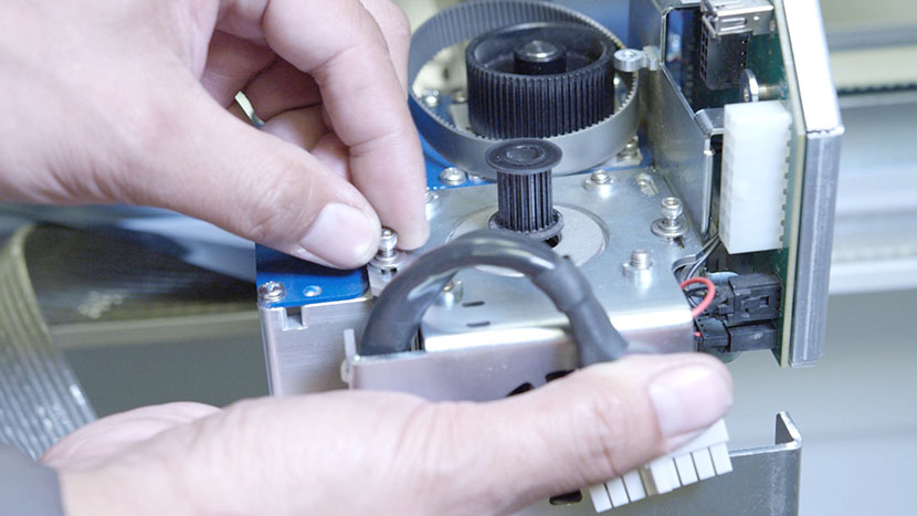
Attach the new x-motor to the x-axis assembly by inserting, but not completely tightening, all four motor mounting bracket screws.
Connect the x-motor’s large white connector to the circuit board.
Press the x-motor in toward the center of the machine and loop the reducer drive belt around both the x-motor and x-axis assembly pulleys. Release the x-motor and let the tensioning spring push it outward so the reducer drive belt goes taut.
Tighten all four motor mounting screws.
Reattach the blue cable guard by screwing in the top Phillips head screw near the rear of the guard and the two Phillips head screws at the front bottom edge of the guard.
Reconnect the X-Axis Assembly
Lift the x-axis assembly and shift it back to the left. Place it on its mounting points, lining up with the guide pins so there is no space between the bottom of the assembly and the screw mounts.
Use a screwdriver to tighten the green captive screws on both ends of the assembly.
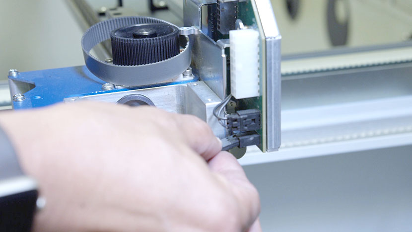
Next, connect the wire harness by plugging in the black and white connectors.
Retrieve the wire harness clamp and position the wire harness and its plastic guard so that the harness is on top of the guard and both are under the clamp on the x-axis assembly. Be sure that the wires between the wire harness and the circuit board have some slack and are not drawn tight.
Secure the clamp by inserting the two screws with a screwdriver.
Reinstall Side Panels
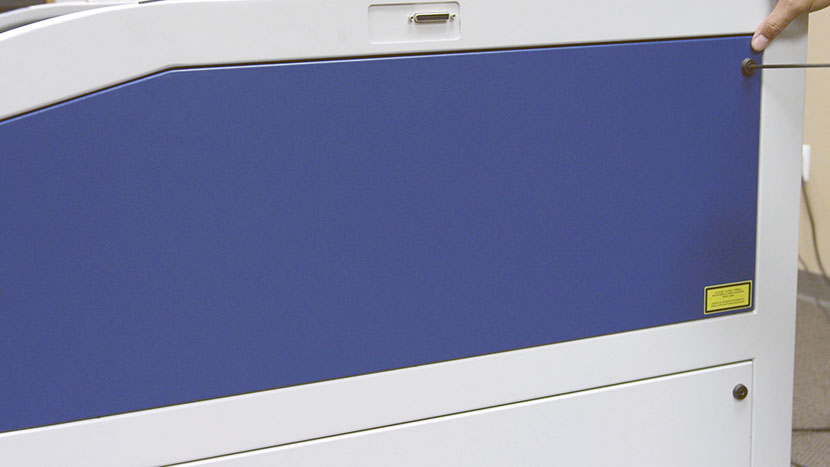
Replace the top access panel on the right side of the machine, using a 5/32” hex key to turn the black panel locks ¾ of the way clockwise.
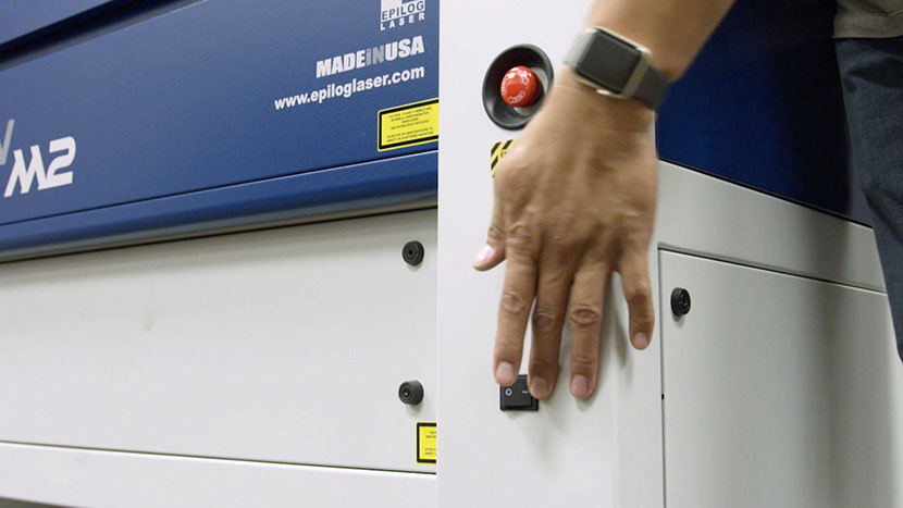
Plug the machine in and turn it on.
Once complete, run an engraving test to ensure the results look correct. If you notice any issues, check that everything is plugged in and positioned properly, and that the tension on the reducer driver belt is adequate.