Introduction
This guide outlines the step-by-step process for replacing the X-axis belt on your laser machine. Before beginning, ensure the machine is powered off and properly prepared for service. Each section includes detailed instructions and corresponding images to help you complete the procedure safely and efficiently. Please follow all notes and cautions carefully to avoid damage or misalignment during reassembly.
Preliminary Steps
- Disconnect the machine from its power source.
- Remove both the left and right hand side upper access panels.
- Remove the top cover from the X-axis assembly.
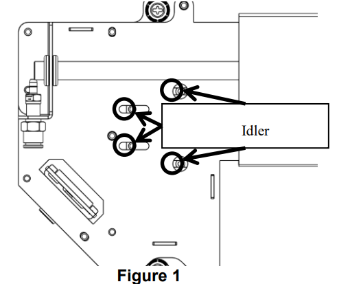
- Loosen the X-axis Idler: Loosen the X-axis Idler Mounting screws circled in Figure 1.
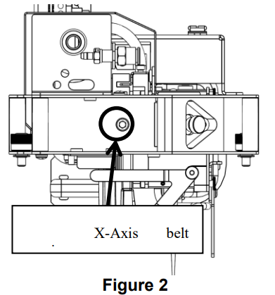
- Remove the tension from the X-axis belt by loosening the screw, circled in Figure 2.
Note: Do not remove this screw, it will be very hard to reinstall.
Remove the Left Side Belt Clamp
- Move the lens carriage to the far right hand side of the machine.
- Locate the X-axis belt clamps. They are located just to the left and the right hand sides of the lens carriage assembly.
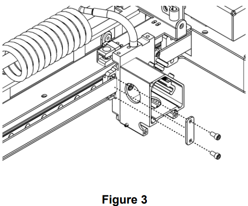
- Remove the left side X-axis Belt clamp (see Figure 3).
Connect the Belts Together
- Overlap one end of the new belt with the end of the old belt that was just removed. Duct tape works best, but masking tape will work in a pinch. Be sure to have the belt oriented in the same manner as the one being removed, teeth to the inside.
- Carefully, by hand, move the lens carriage to the left. This will start pulling the new belt into place. Once there is sufficient belt available on the right-hand side of the lens carriage, you can grasp the belt by hand and gently pull it the rest of the way through the right-hand side of the rail.
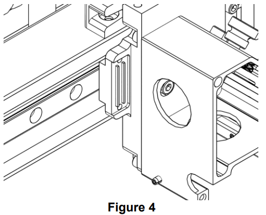
- Separate the two belts and take the free end on the left-hand side of the rail assembly and install the belt on the left-hand side of the lens carriage. Note that the teeth of the belt fit into the teeth cut in the lens block (see Figure 4).
Install the Belt Clamps
- Once the belt has been fitted into the lens block assembly, reinstall the belt clamp and tighten the clamp screws (see Figure 3).
- Fit the right-hand side of the X-axis belt into the teeth of the right-hand side of the lens block assembly and mount the right-hand side X-axis belt clamp.
Applying Tension to the X-Axis Belt
- Begin to apply tension to the X-axis belt via the X-axis belt tension screw that was loosened earlier.
- Remove the slack from the X-axis belt.
- Once the slack is removed, open the graphics art program and place a short line of capital T’s in Times New Roman on the page to be engraved. Engrave the line. Look closely at the Serifs of the T and verify good registration of the image.
- Poor registration would be seen as the Serifs of the T not lining up. If the Serifs are not aligned, add a little tension to the X-axis belt.
- Repeat this process until the Serifs of the T are properly aligned.
Was this helpful?
Thanks for your feedback!