Welcome to the Zing Laser Series, Epilog’s entry-level, small format, high-quality engraving line. Perfect for everything from home use to starting a business.
Control Panel
It all starts at the keypad. Our easy-to-use control panel allows you to access your job, start and stop the laser, focus for your project, and much more. On the LCD panel, you will see any current jobs at the machine. You can scroll through these jobs to the one you want to run.


Vector Cutting Grid
(Optional Feature) Here is the optional vector-cutting grid. This robust table with metal grid allows you to cut through all kinds of materials with minimal backside burning.

Engraving Table
(Standard Feature) When the cutting table is removed, here is your engraving table. When you’re not vector cutting, the engraving task plate provides a level flat surface for optimal engraving quality across the entire work area of your laser system. The table has two guide rulers that help with placement of your objects at the top left corner of the engraving table.

X-Axis Assembly
Here we have the I-beam, or X-Axis Assembly. It will initially be parked outside the engraving area, so you have better access to the laser bed to place items on the table. The I-beam is what carries the laser’s lens assembly, which slides left and right in a sweeping motion in the X-Axis direction.


Along the I-beam, you will find a series of holes along the bottom of the rail. This is the Air Assist curtain, which directs a constant stream of compressed air along the cutting surface, reducing the possibility of flaming, scorching, or charring when cutting through materials. The Air Assist curtain must be used in conjunction with a standard compressed air supply, or the optional standalone compressor offered by Epilog.

Lens Assembly
On the lens assembly, you will find the industrial-grade mirrors and lens, rated to over 500 watts. These are an integral part of Epilog’s optics system. It consists of a mirror that reflects the laser beam down through a focal lens.


Keeping your laser optics clean will help them perform their best, and it starts with fully accessible front-mounted mirrors that can be easily removed.

The spring-based manual focus gauge can be swung down as you focus the table to the correct height, then swung back to position out of the way on the I-beam.

Exhaust
At the back of the laser system, you will find the exhaust plenum. The top three slots are where the engraving area will be exhausted of all of the smoke, dust, and debris resulting from your engraving and cutting. The bottom three holes line up with the optional vector cutting grid, which operates as a vacuum suction table, pulling the air through the bottom of the cutting table.


Front Access Door
On the Zing 24, you’ll find the drop-down front door. This safety-interlocked door allows you to easily place larger items on the table through the front of the system.

Status Lights and Ports
On the right side of the laser is the system status lights. These will be used by technical support for diagnosis of issues.

Next to the system status lights you’ll find the auxiliary port and the Ethernet and USB ports that are used to connect your laser system to your computer.

At the bottom right corner of the side panel, you’ll find the main power switch, two AC breakers and where your power cord is attached to the system.

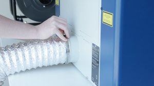
System Rear
Moving on to the back of the laser system, you’ll find a 4-inch exhaust plenum to which you’ll attach your exhaust fan or filtration system.

The anodized plate at the bottom right corner of the system is where you will find your serial number, which you will need if you find it necessary to contact Technical Support.

Air Intake
The left side of the system has six air intake holes for the laser’s heat sink fans.

Interior System Components
As we remove the right side panel of the system, we can see the inner workings of the machine.

Here you will find the DC power supply and X-Axis Motor. Here you can also see the Y-Axis rail and belt, as well as the Z-Axis Motor.
.")

Under the top panel on the back of the system, you can see the Y-Axis drive system that moves the laser assembly forward and back, as well as the fan control board.

The bottom panel on the back of the system can be removed for easy cleaning of the inside of the exhaust area of the system.

Under the left access panel, we find the Y-Axis rail and belt. These allow the laser to move accurately from the front to the back of the system.

Here is the heart and soul of your laser machine. The CO2 laser tube.

This was a quick look at the inner workings of your Zing laser machine. Now it’s time to start engraving.
Zing Manual Download
To check out more of the Zing Laser features and capabilities, download the Zing Laser Manual.