
Linear Guide Replacement (IKO) – Pro 48 Large Aperture

X-Axis :


Introduction

This guide provides step-by-step instructions for removing and replacing the X-Axis Linear Guide (IKO) in a large-aperture Fusion Pro 48 laser system. Follow each step carefully to ensure a safe and efficient procedure. Always disconnect power before beginning any maintenance.

Removal

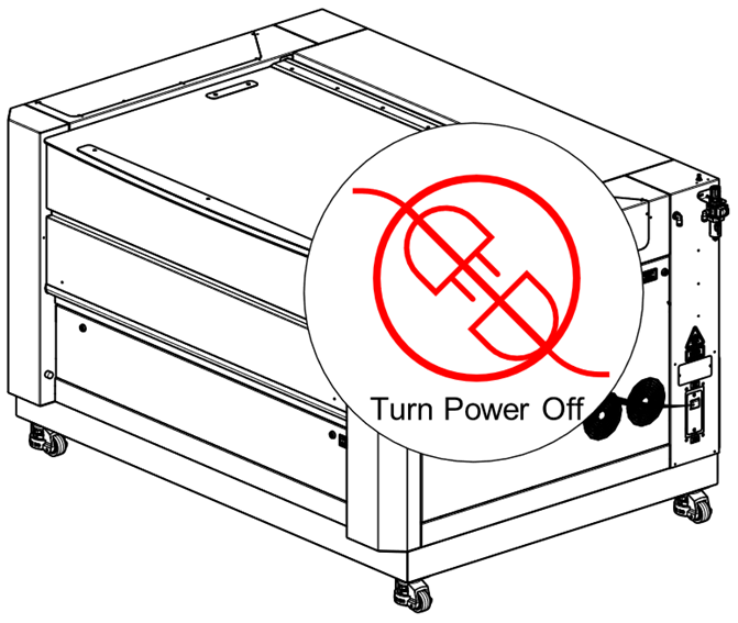
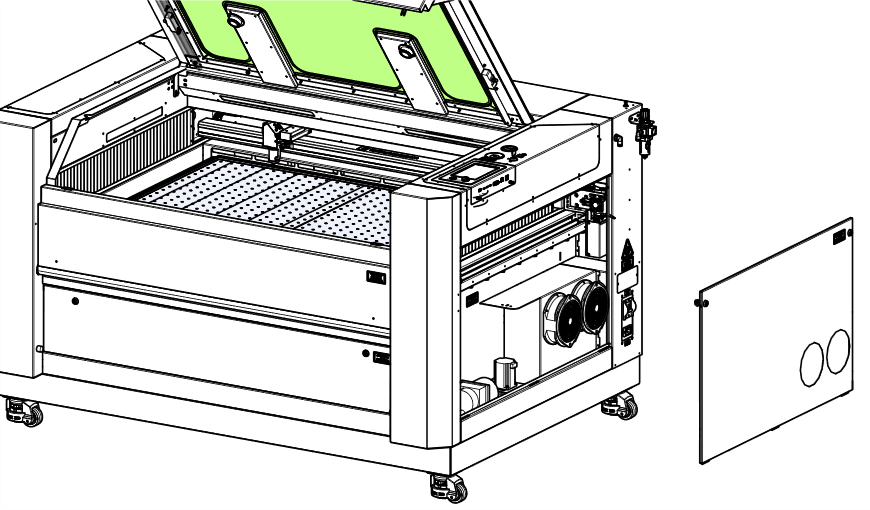
  1. Power off the machine and disconnect the power cable.

    Machine being powered off and unplugged

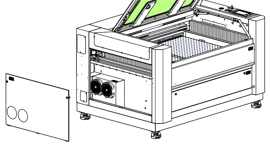
  2. Remove the right and left side panels.

    Removing the right side panel of the laser machine
    Removing the left side panel of the laser machine

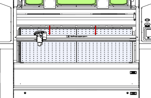
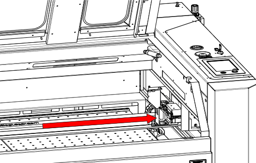
  3. Move the X-Axis rail to the center of the machine.

    X-Axis rail centered on the machine

  4. Move the carriage to the center of the machine.

    Carriage positioned at the center of the machine

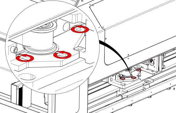
  5. Loosen the tensioner bracket screws.

    Loosening the tensioner bracket screws

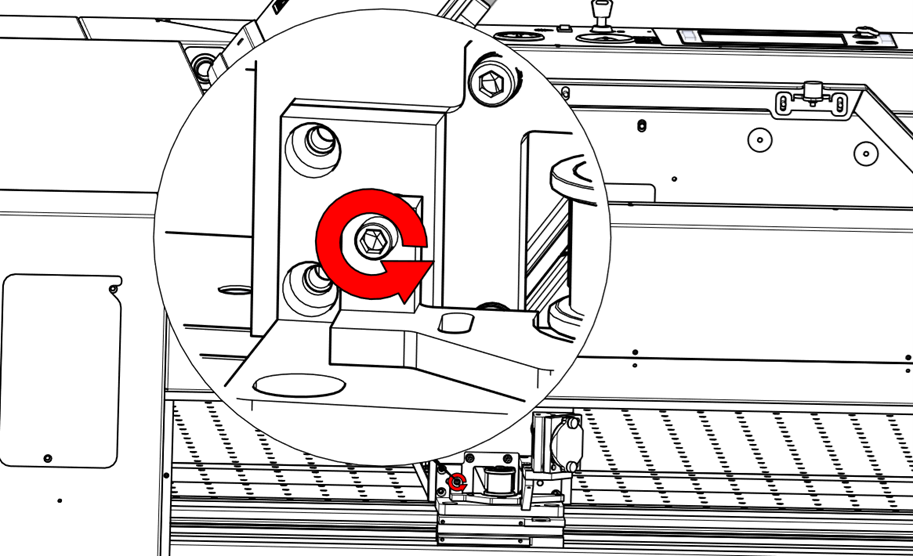
  6. Loosen the tensioner screw.

    Loosening the tensioner screw

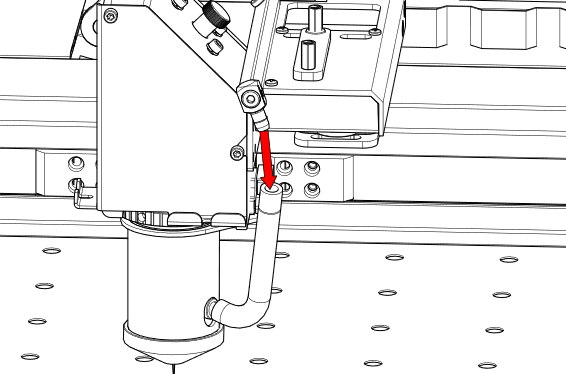
  7. Remove the air assist tubing.

    Air assist tubing being removed

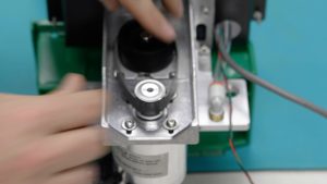
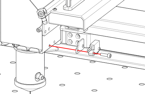
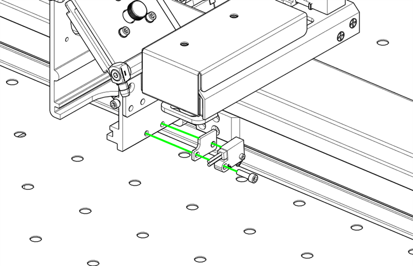
  8. Remove the autofocus switch.

    Removing the autofocus switch

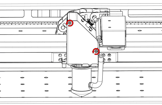
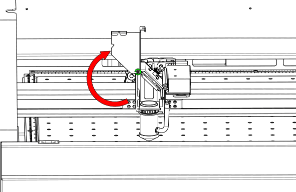
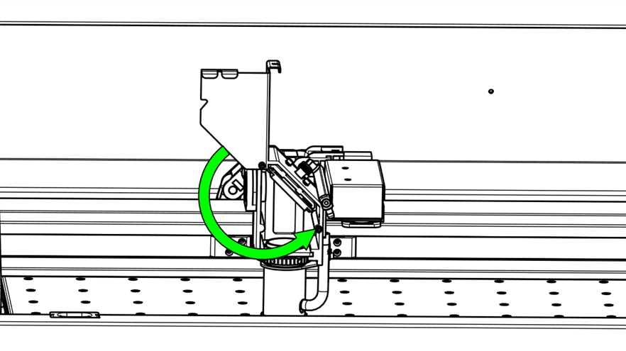
  9. Loosen the carriage cover screws and open the cover.

    Loosening screws on the carriage cover
    Opening the carriage cover

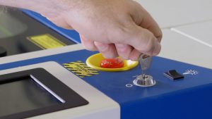
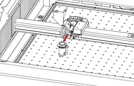
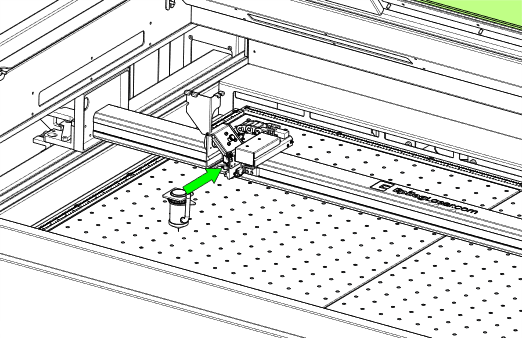
  10. Loosen the lens nut and remove the lens.

    Removing the lens from the carriage

  11. Move the carriage to the right side of the machine.

    Carriage moved to the right side of the machine

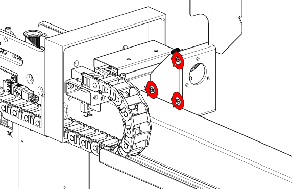
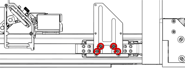
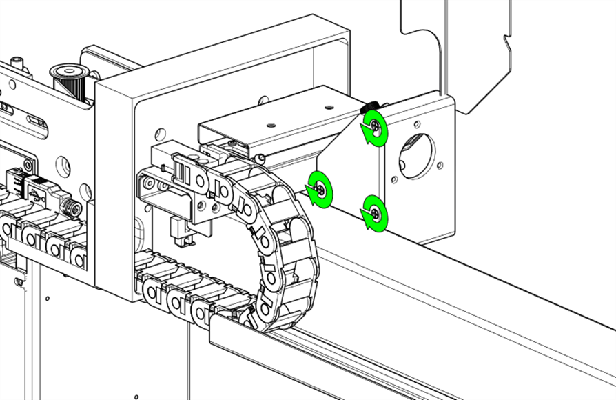
  12. Remove the screws on the back of the carriage mirror housing.

    Screws being removed from the carriage mirror housing

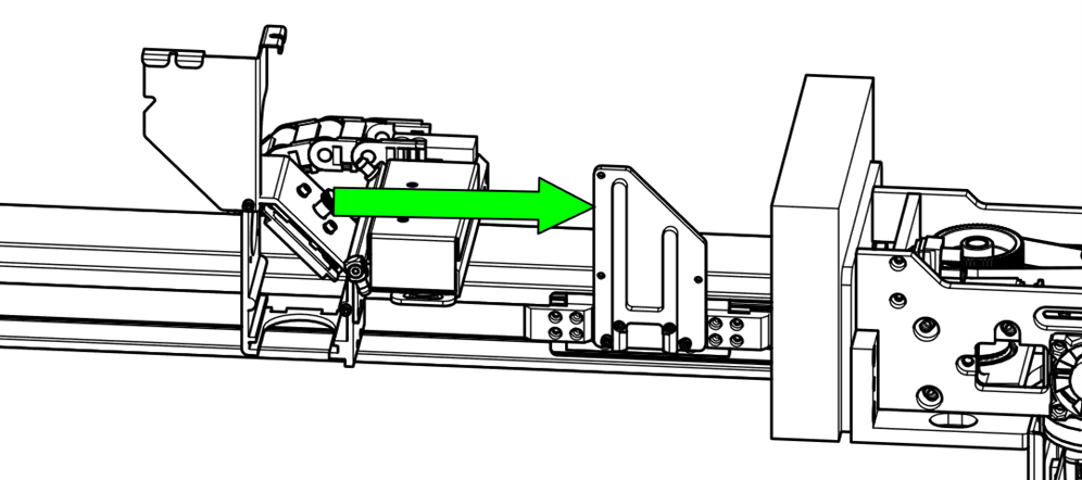
  13. Move the carriage to the left side of the machine.

    Carriage moved to the left side of the machine

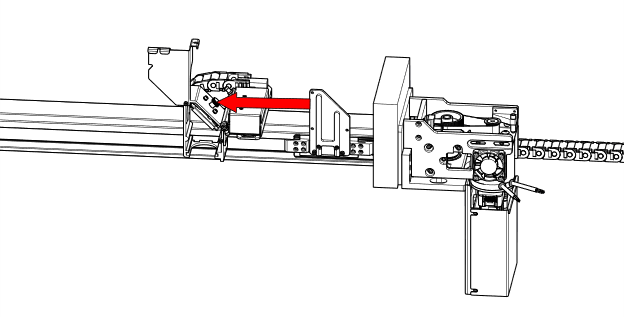
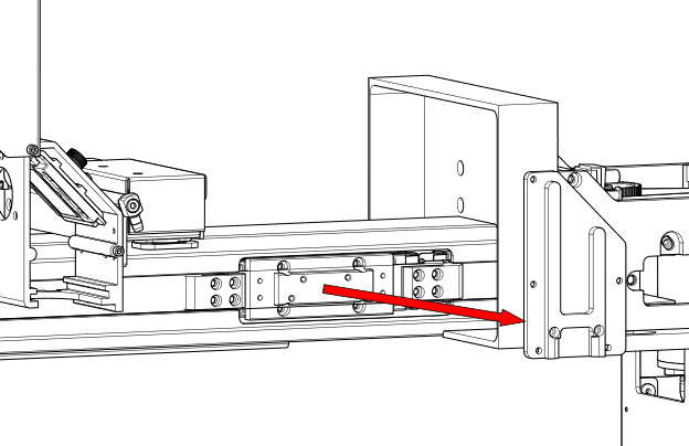
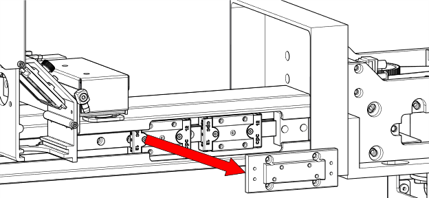
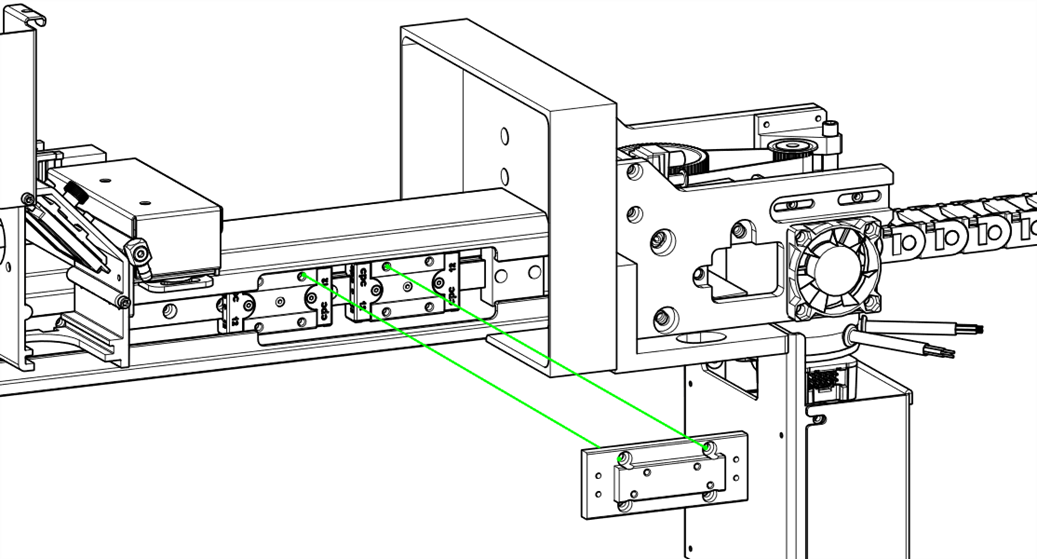
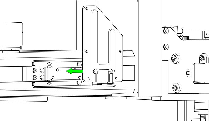
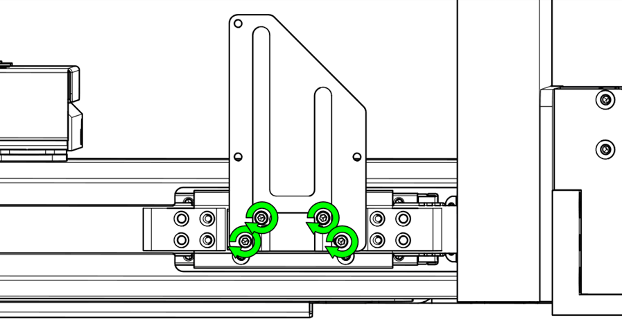
  14. Remove the carriage mounting plate.

    Removing the carriage mounting plate
    Carriage mounting plate detached

  15. Remove both ends of the belt.

    First belt end being removed
    Second belt end being removed

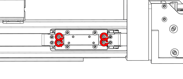
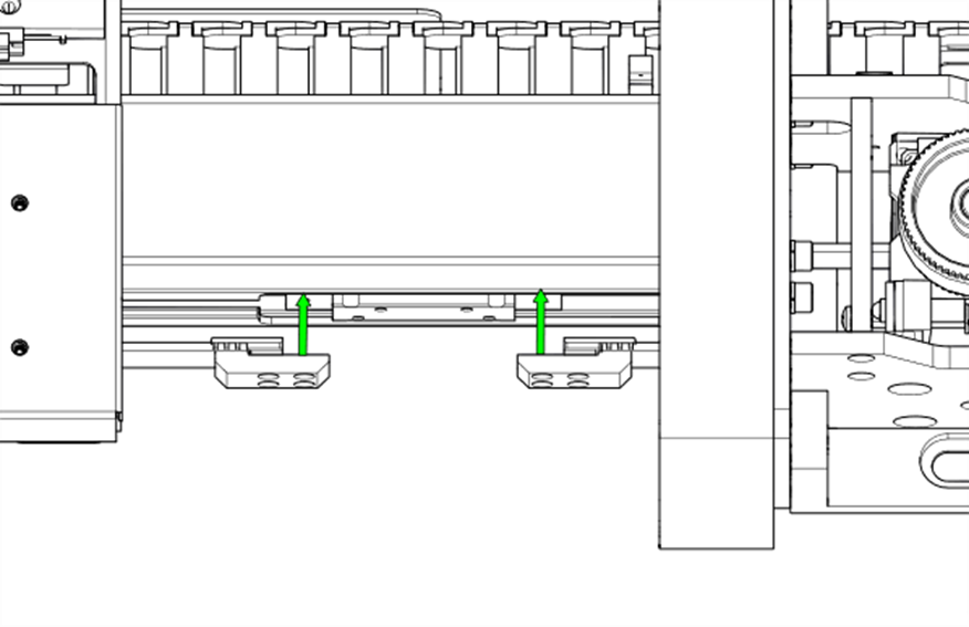
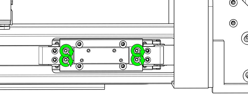
  16. Remove the bearing plate.

    Bearing plate being removed

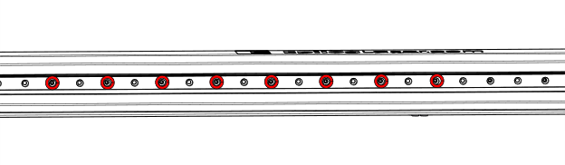
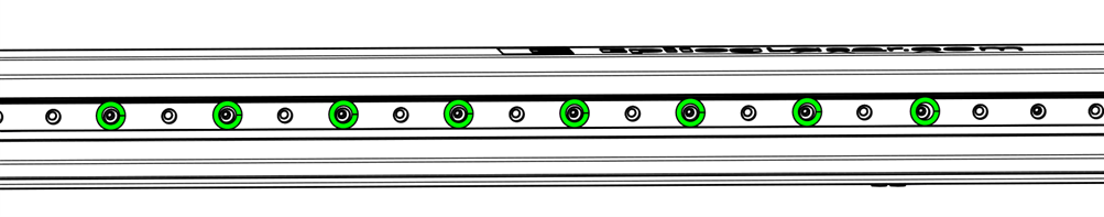
  17. Remove the linear guide mounting hardware.

    Removing mounting screws from the linear guide

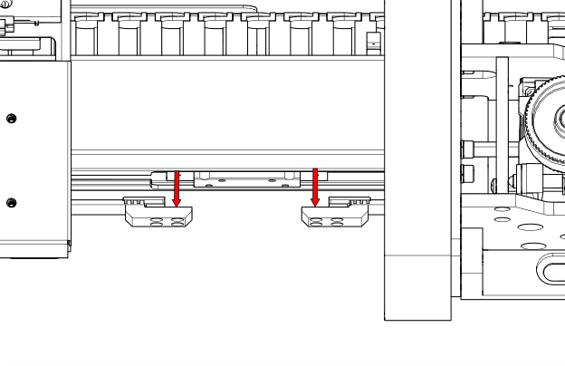
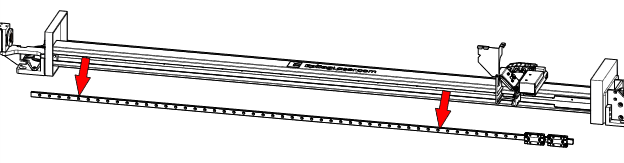
  18. Remove the linear guide.

    Linear guide being removed from the machine

Installation

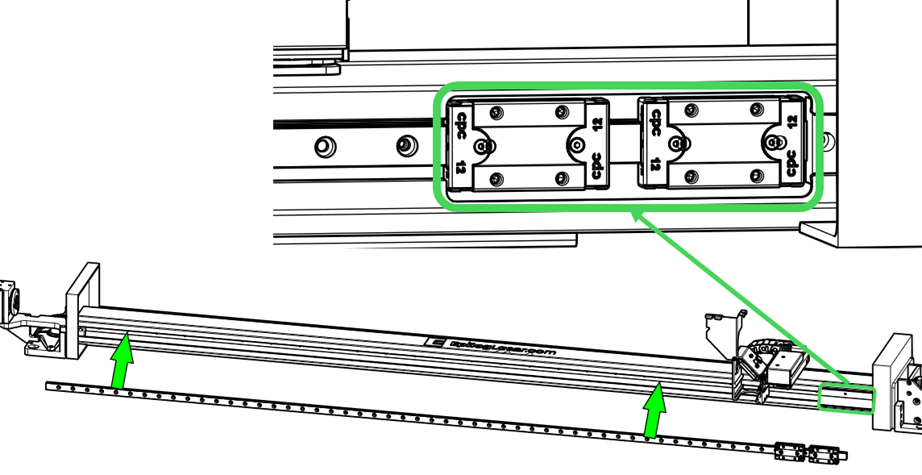
  1. Install the linear guide with bearing blocks positioned at the cutout.

    Positioning linear guide with bearing blocks at cutout
    Linear guide in place with bearing blocks aligned

  2. Install the bearing plate.

    Installing the bearing plate

  3. Install the belt.

    First side of the belt being attached
    Second side of the belt being attached

  4. Install the carriage mounting plate.

    Mounting plate being attached to the carriage
    Mounting plate installed on the carriage

  5. Attach the carriage to the mounting plate.

    Carriage being secured to mounting plate
    Fully mounted carriage on the plate

  6. Install the autofocus switch.

    Reinstalling the autofocus switch

  7. Install the lens and tighten the lens nut.

    Lens being installed and nut tightened

  8. Close the mirror cover and tighten the thumb screws.

    Mirror cover closed and thumb screws secured

  9. Note: Follow the Belt Tensioning Guide to retension the belt before replacing the side panels.
  10. Reinstall the right and left side panels.

    Reinstalling the right side panel
    Reinstalling the left side panel

  • ID:
    KA-01683
  • Date:
    06/02/2025

Tools:

  • 5/32" Hex Wrench
  • 3/32" Hex Wrench

Parts & Resources:

  • CS0489 Linear Guide Pro 48