
X-Axis Reducer Drive Replacement (Large Aperture)

X-Axis :


Introduction

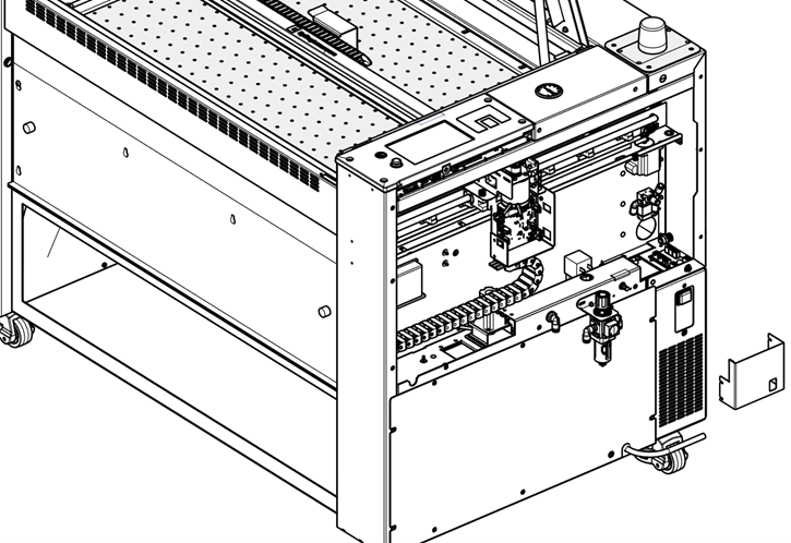
This guide provides detailed instructions for the removal and installation of the X-Axis assembly and reducer drive components on a Fusion Pro laser system with a large aperture. Carefully follow each step to ensure a safe and effective procedure. Always disconnect power before beginning any maintenance.

Removal

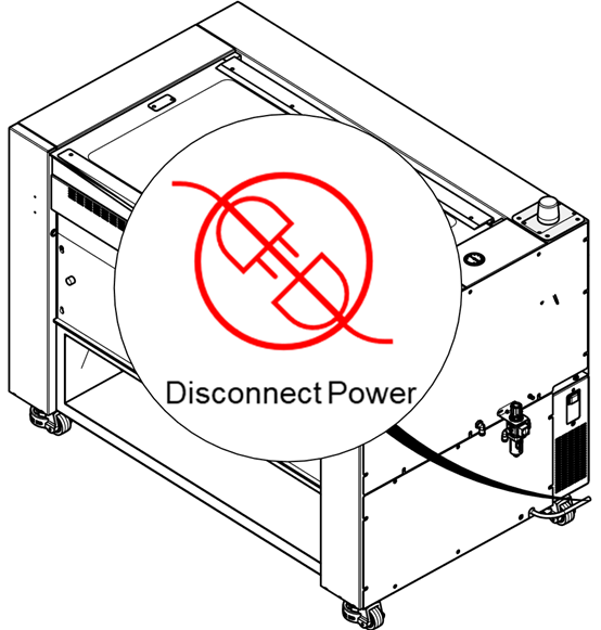
  1. Power off the machine and disconnect the power cable.

    Powering off and unplugging the laser system

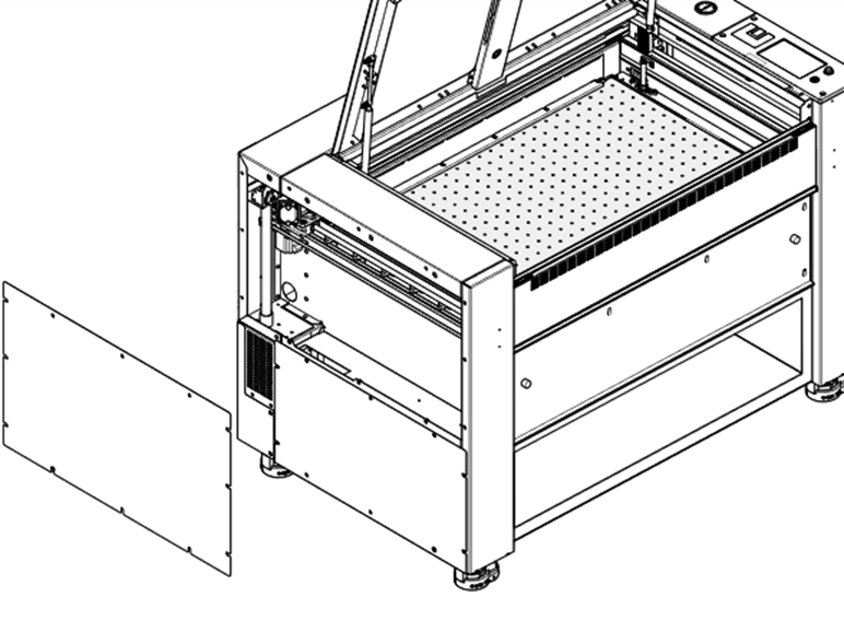
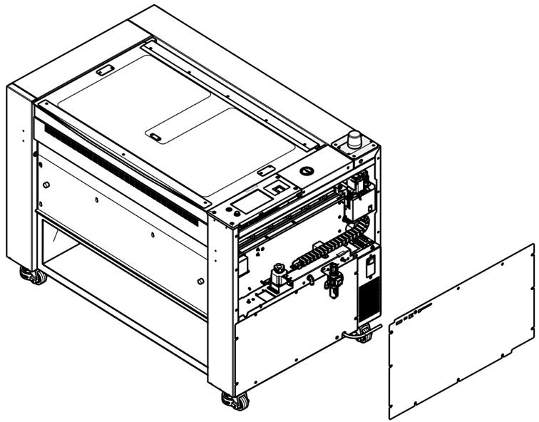
  2. Remove the right and left side panels.

    Removing the right side panel
    Removing the left side panel

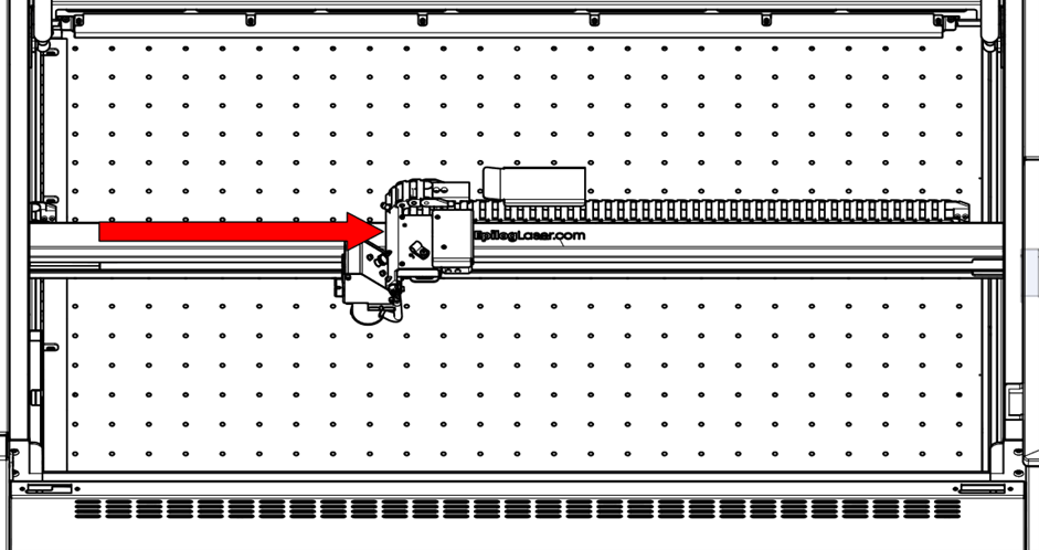
  3. Move the X-Axis rail to the center of the machine.

    Positioning the X-Axis rail to the center

  4. Move the lens carriage to the center of the machine.

    Centering the lens carriage

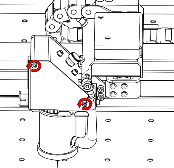
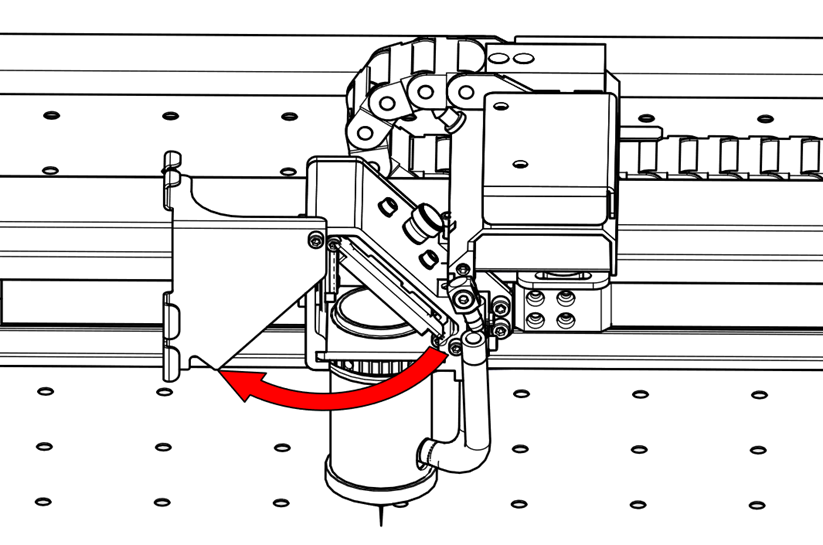
  5. Loosen the thumb screws and open the carriage mirror cover.

    Loosening thumb screws on carriage mirror cover
    Opening carriage mirror cover

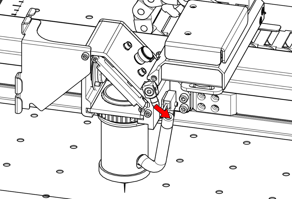
  6. Disconnect the air assist tubing.

    Disconnecting air assist tubing from carriage

  7. Remove the lens from the carriage.

    Removing the lens from carriage

  8. Close the carriage mirror cover.

    Closing the carriage mirror cover

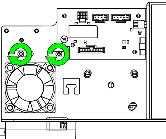
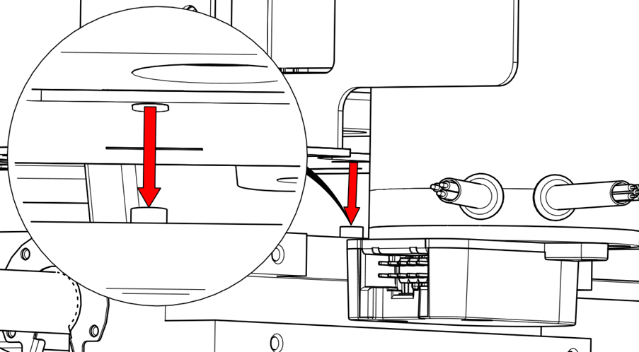
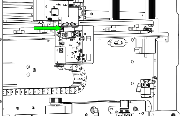
  9. Remove the X-Axis drive board cover.

    Removing X-Axis drive board cover

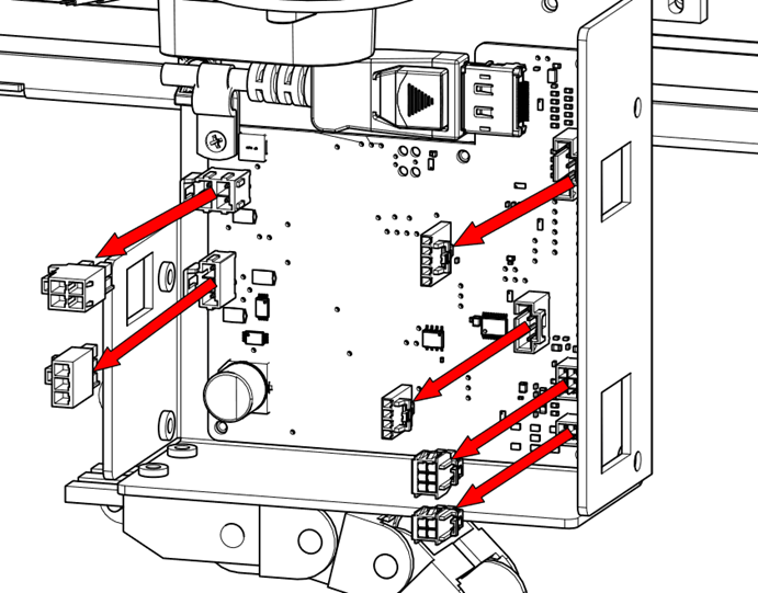
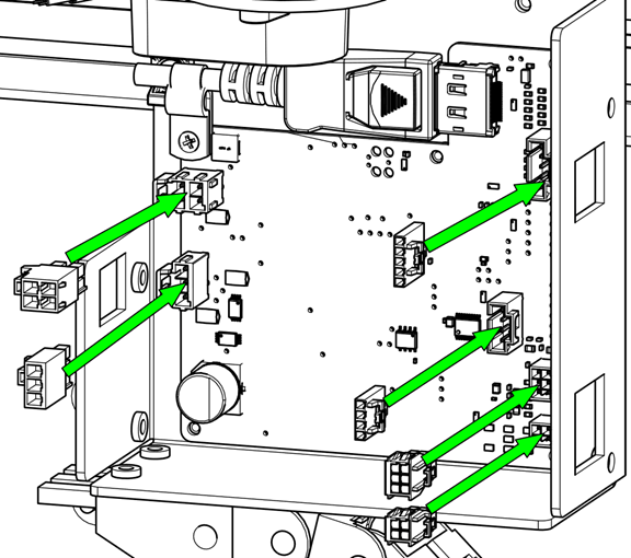
  10. Disconnect the electrical harnesses from the X-Axis drive board and motor.

    Disconnecting electrical harnesses from X-Axis drive board
    Step 10

  11. Disconnect additional air assist tubing if present.

    Disconnecting auxiliary air assist tubing

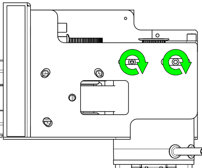
  12. Remove the mounting screws from the X-Axis drive board mounting plate.

    Removing mounting screws from drive board plate

  13. Remove the drive board and mounting plate.

    Removing X-Axis drive board and plate

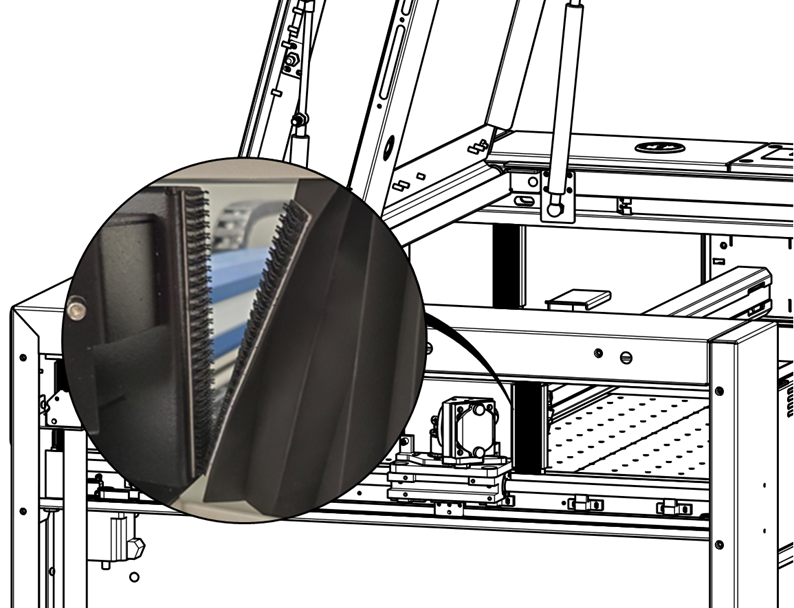
  14. Disconnect the Velcro bellows from the X-Axis assembly.

    Detaching Velcro bellows

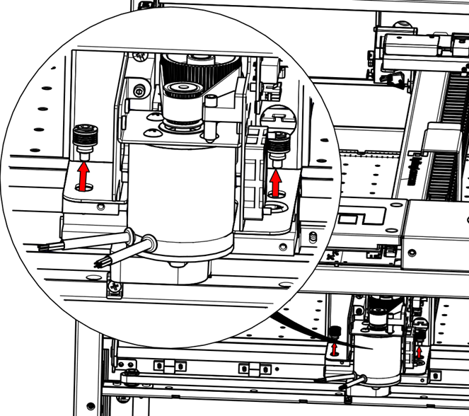
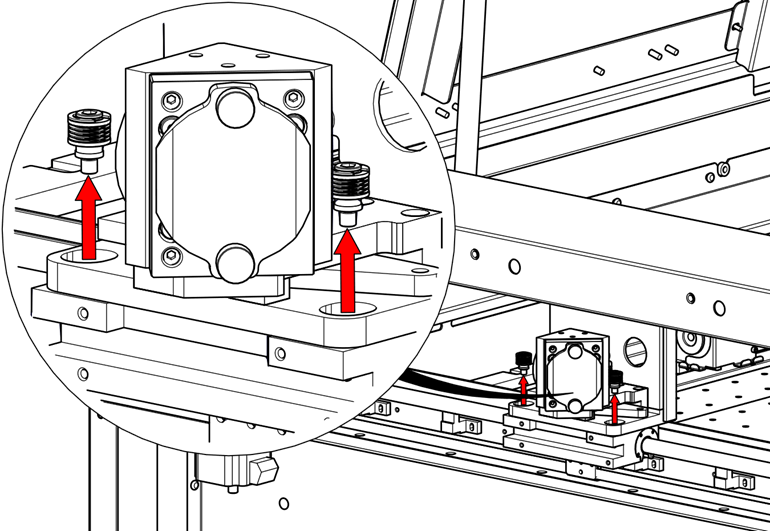
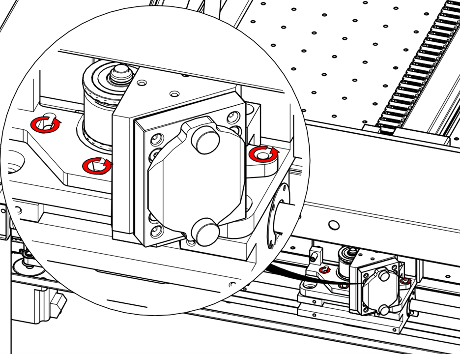
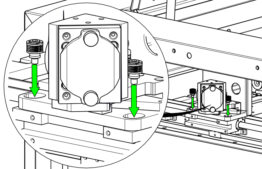
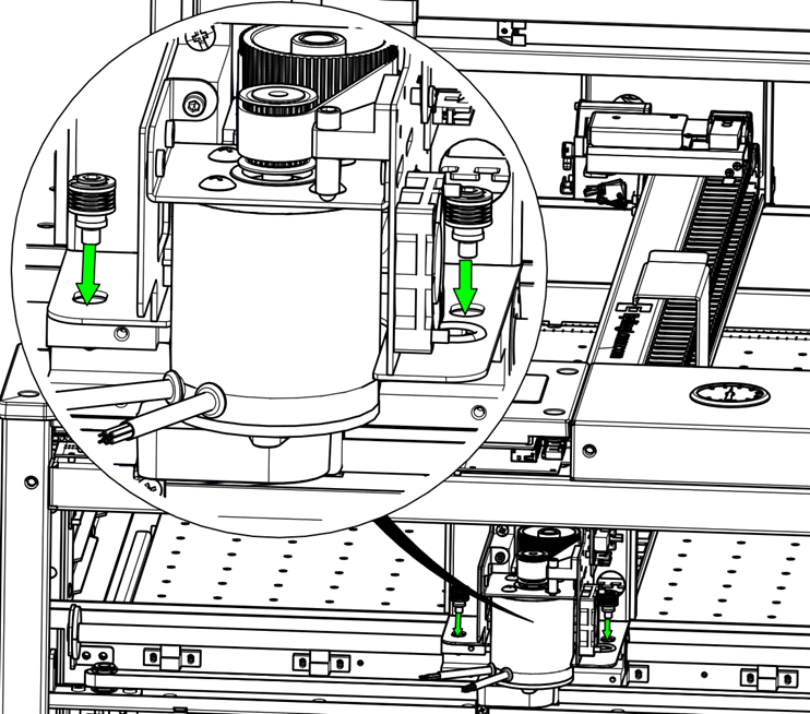
  15. Remove the mounting hardware from both sides of the X-Axis rail.

    Removing X-Axis hardware on left side
    Removing X-Axis hardware on right side

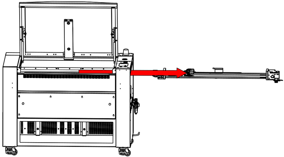
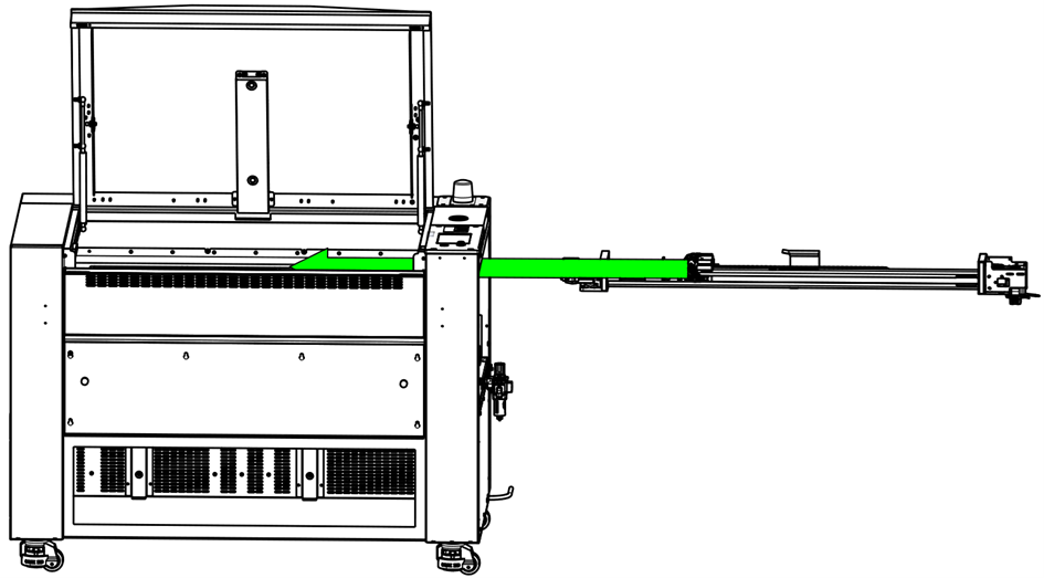
  16. Lift and remove the X-Axis assembly. Place it on a suitable repair bench.

    Removing and placing X-Axis assembly on bench

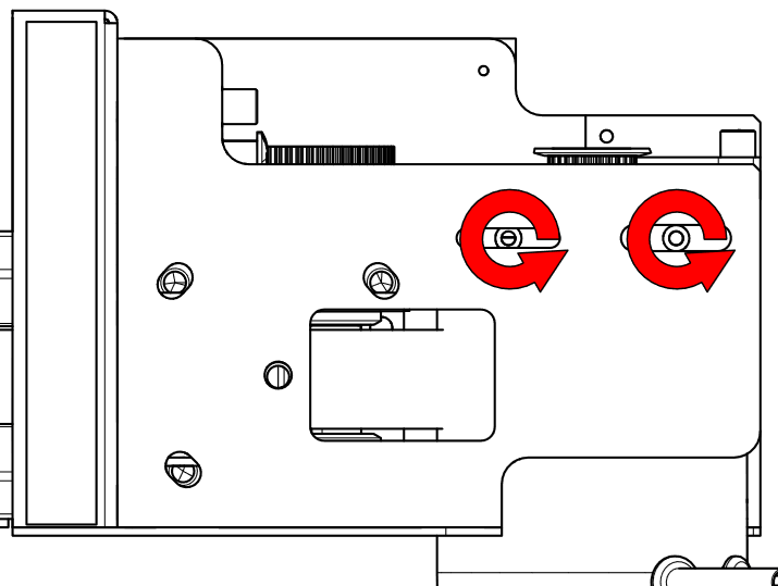
  17. Loosen the belt tension bracket screws.

    Loosening belt tension bracket screws

  18. Loosen the tensioner screw.

    Loosening belt tensioner screw

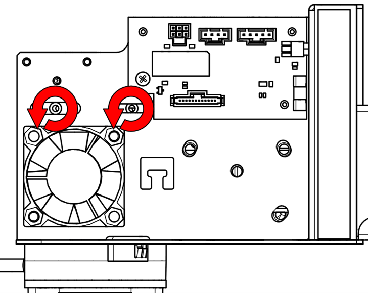
  19. Loosen the motor mounting screws.

    Loosening motor mounting screws
    Loosening motor screws with wrench

  20. Loosen the motor tensioner screw.

    Loosening motor belt tensioner screw

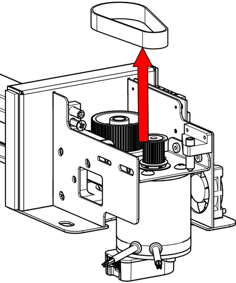
  21. Remove the reducer belt from the pulleys.

    Removing the reducer belt from pulley system

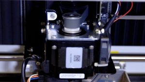
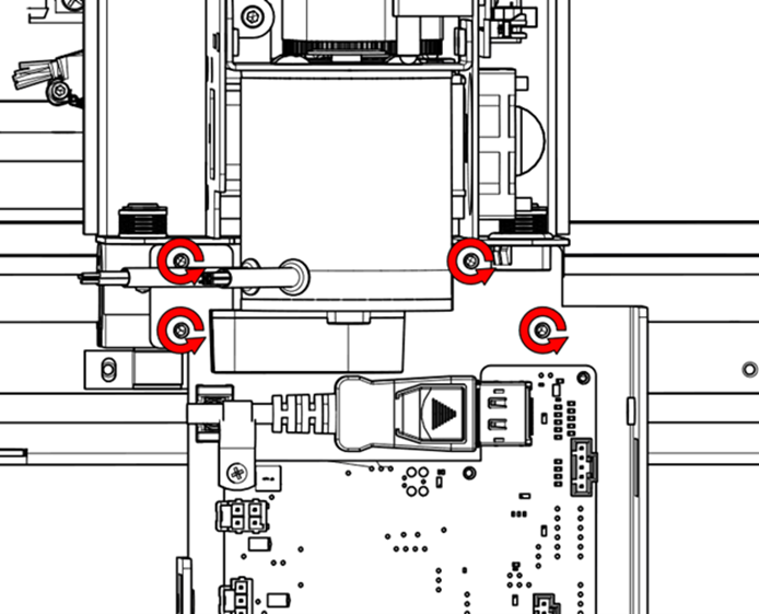
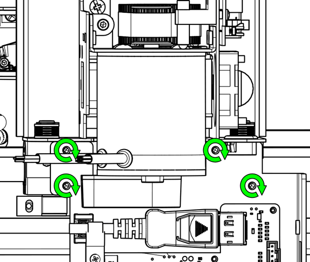
  22. Remove the reducer pulley mounting screws.

    Removing mounting screws from reducer pulley

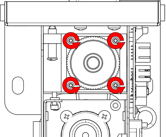
  23. Remove the reducer pulley.

    Removing reducer pulley from motor shaft

Installation

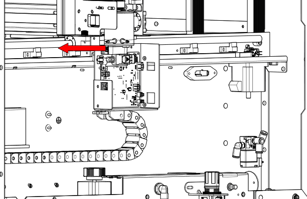
  1. Pull the X-Axis belt toward the motor area.

    Pulling belt toward motor pulley

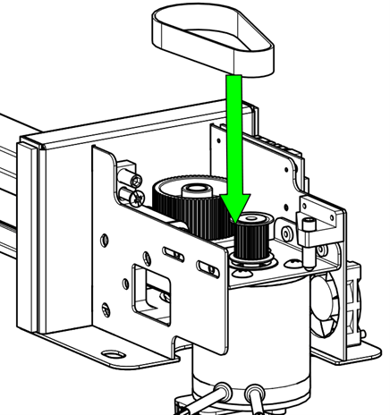
  2. Install the reducer pulley, ensuring the belt wraps around the outside of the pulley.

    Installing reducer pulley and routing belt

  3. Install the reducer pulley mounting screws.

    Securing reducer pulley with screws

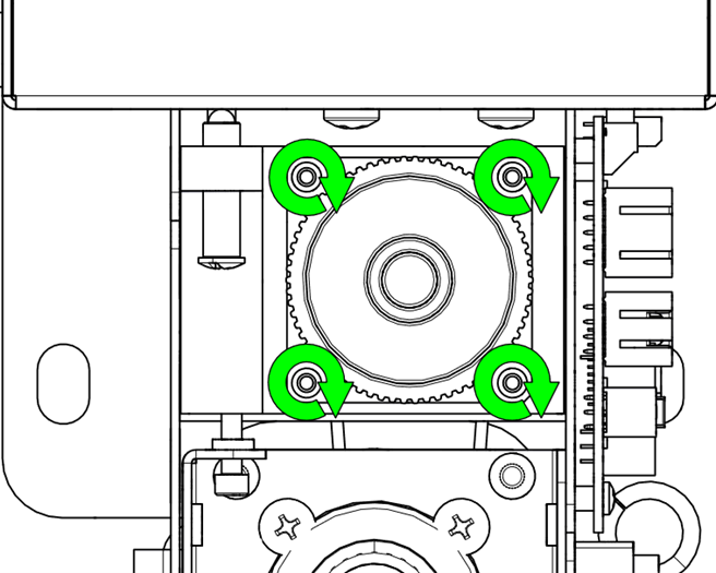
  4. Install the reducer belt onto both pulleys.

    Placing reducer belt on motor and drive pulleys

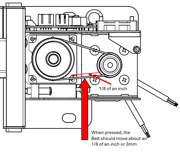
  5. Apply tension to the reducer belt.

    Note: The belt should not be overly tight. When pressed from the side, it should deflect approximately 1/8″ (3 mm).

    Applying proper belt tension
    Checking belt deflection

  6. Tighten the motor mounting screws.

    Tightening motor screws
    Securing motor screws with wrench

  7. Install the X-Axis assembly into the machine.

    Lowering X-Axis assembly into machine

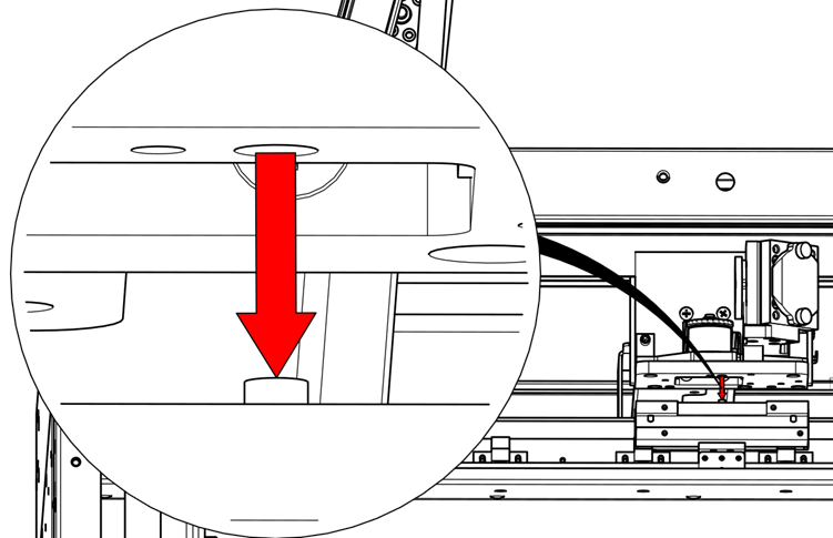
  8. Align the X-Axis with the alignment pins.

    Aligning X-Axis with guide pins
    Fine alignment of X-Axis rail

  9. Install the X-Axis mounting hardware.

    Securing X-Axis with mounting screws
    Tightening X-Axis mounting hardware

  10. Reconnect the Velcro bellows to the X-Axis.

    Reattaching Velcro bellows

  11. Attach the X-Axis drive board mounting plate.

    Installing X-Axis drive board plate

  12. Reconnect the electrical harnesses to the X-Axis drive board and motor.

    Connecting electrical harnesses
    Step 10

  13. Reinstall the X-Axis drive board cover.

    Reattaching drive board cover

  14. Reinstall the right and left side panels.

    Reinstalling right panel
    Reinstalling left panel

  • ID:
    KA-01678
  • Date:
    05/30/2025

Tools:

  • 5/32" Hex Wrench
  • 3/32" Hex Wrench
  • 7/64" Hex Wrench

Continue Your Laser Journey

Revisit a past lesson or move ahead to discover what’s next!