In this video we will walk you through replacing the X-Axis Assembly on the Fusion Pro.
X-Axis Assembly Removal
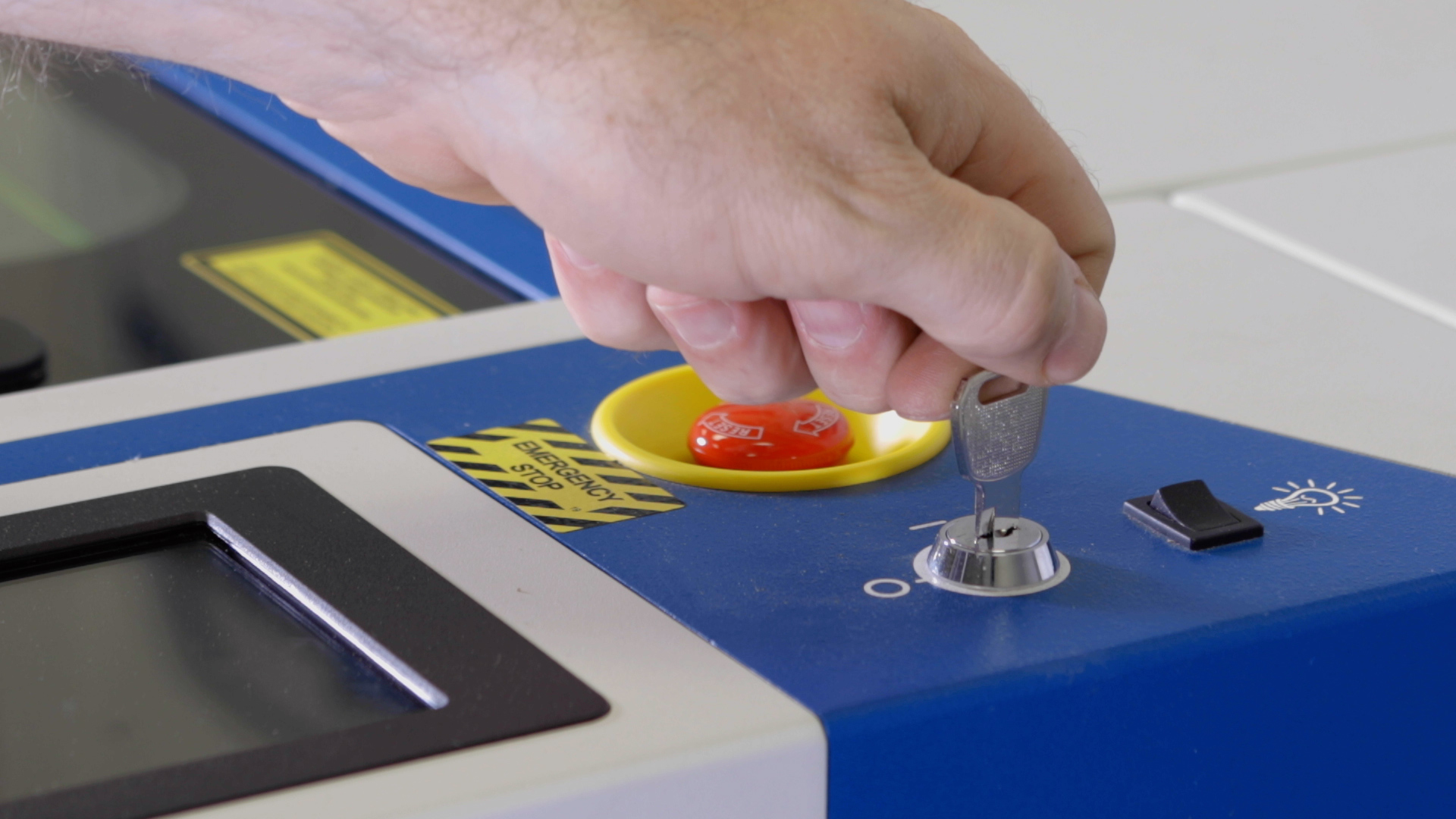
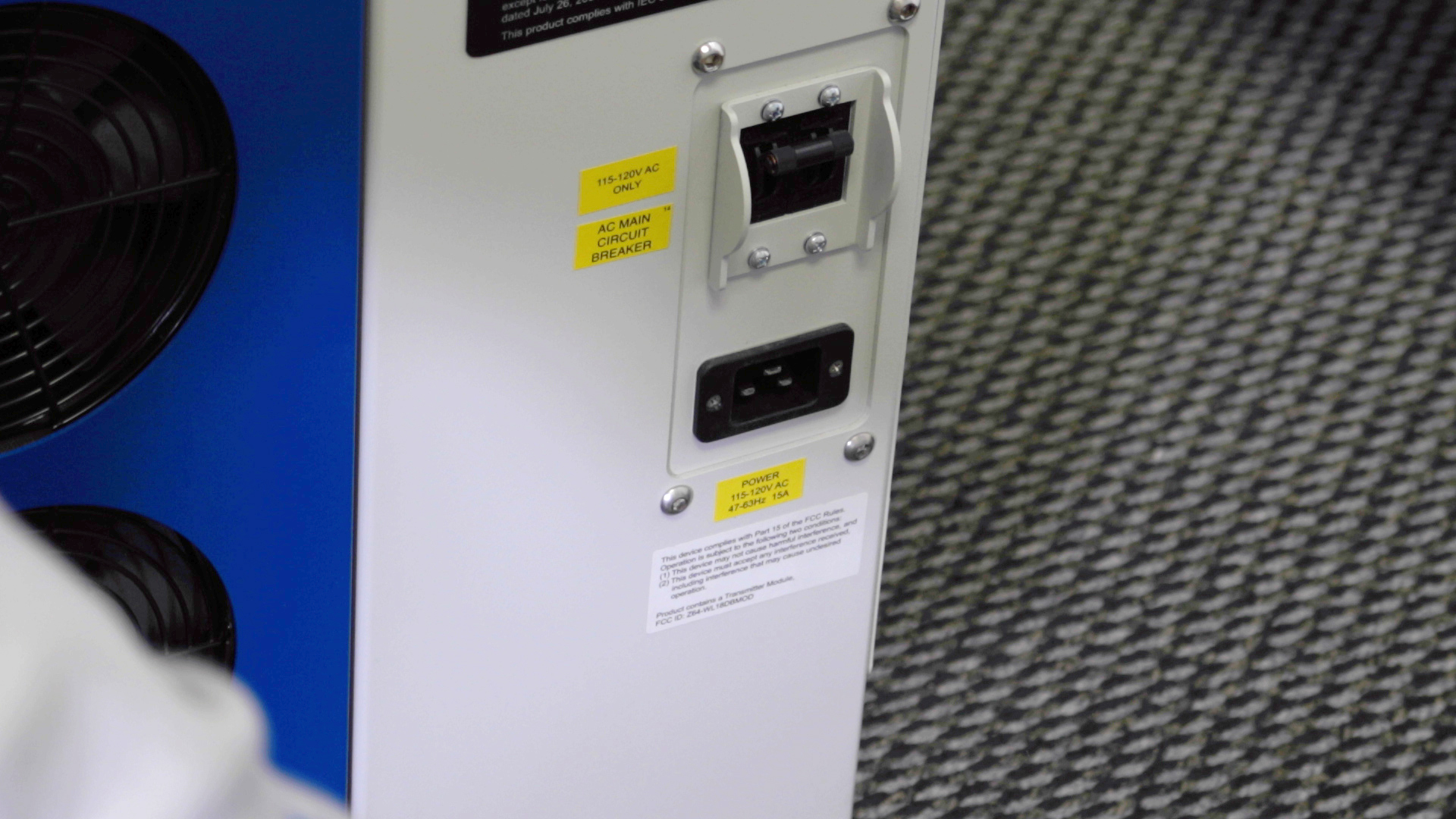
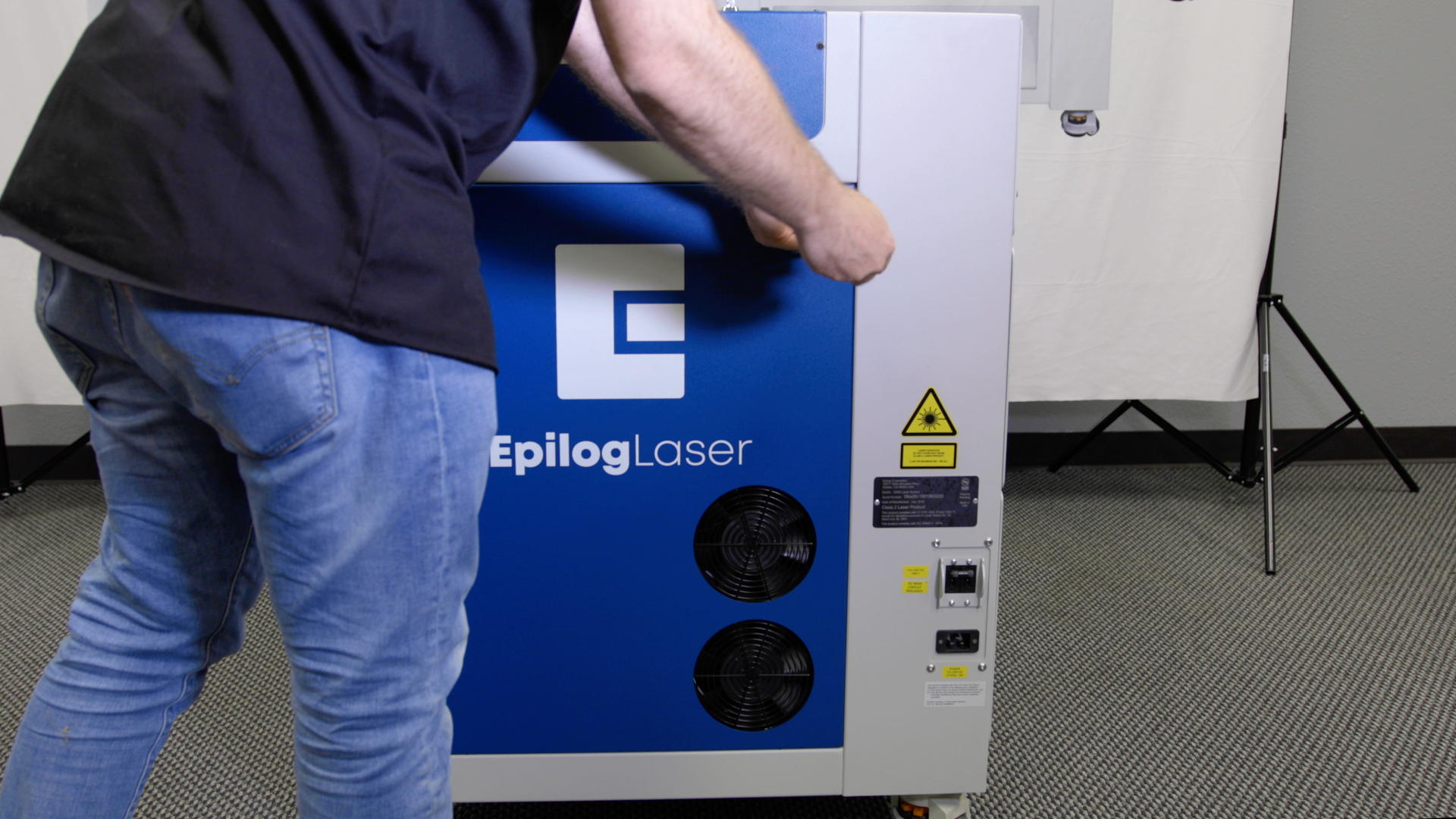
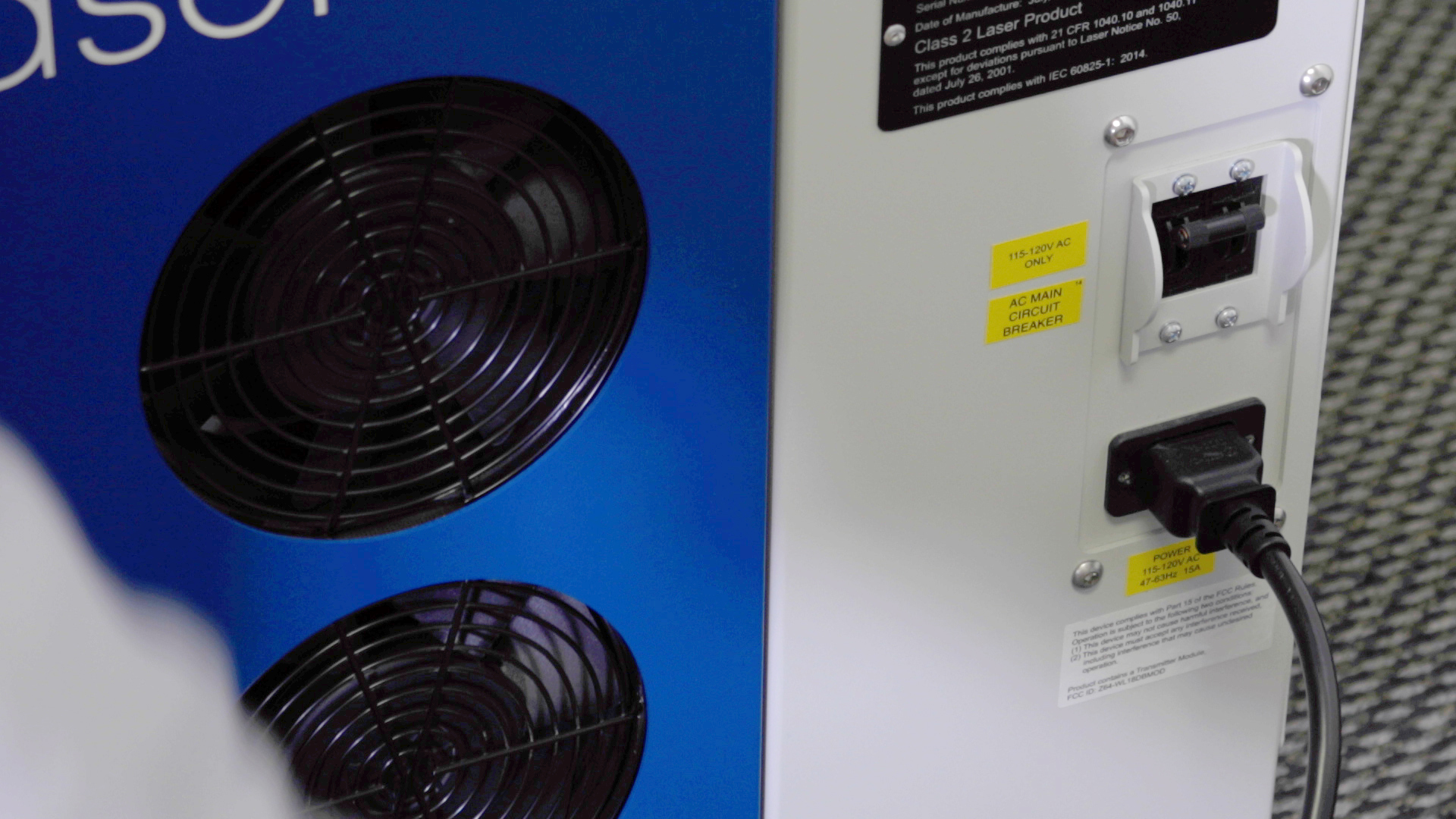
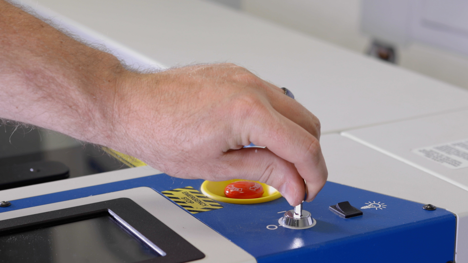
First, power off and unplug the machine.
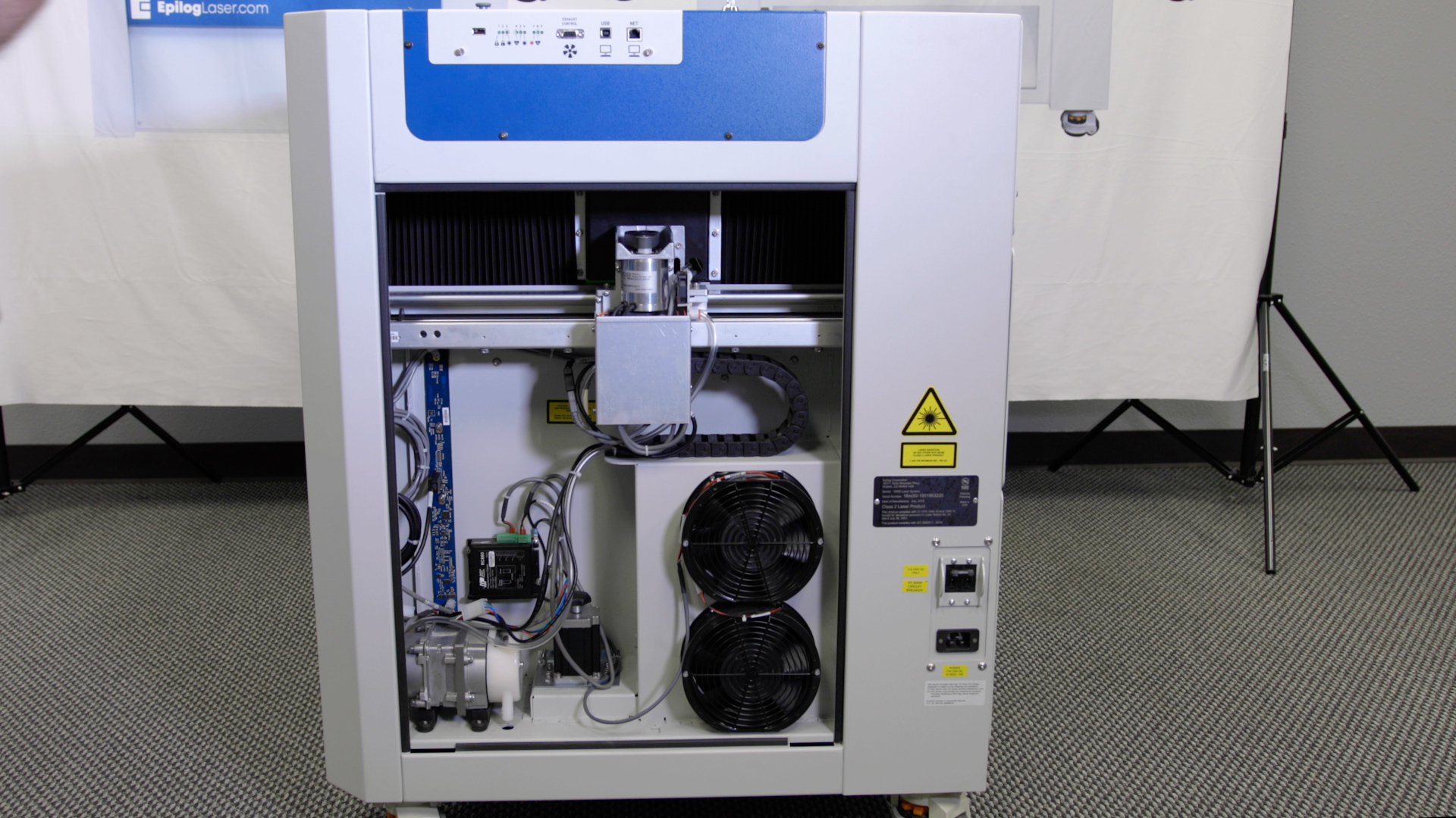
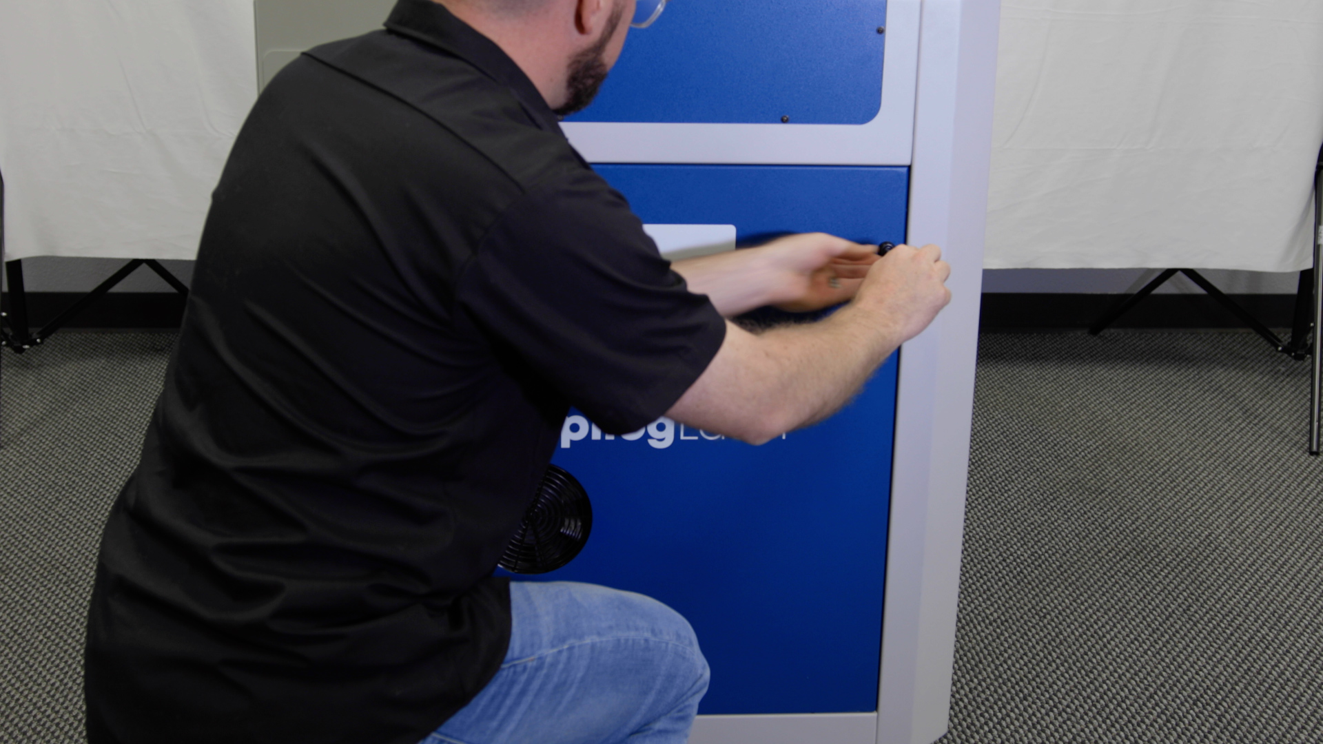
Using a 5/32” Allen Key, remove the right side panel from the machine.
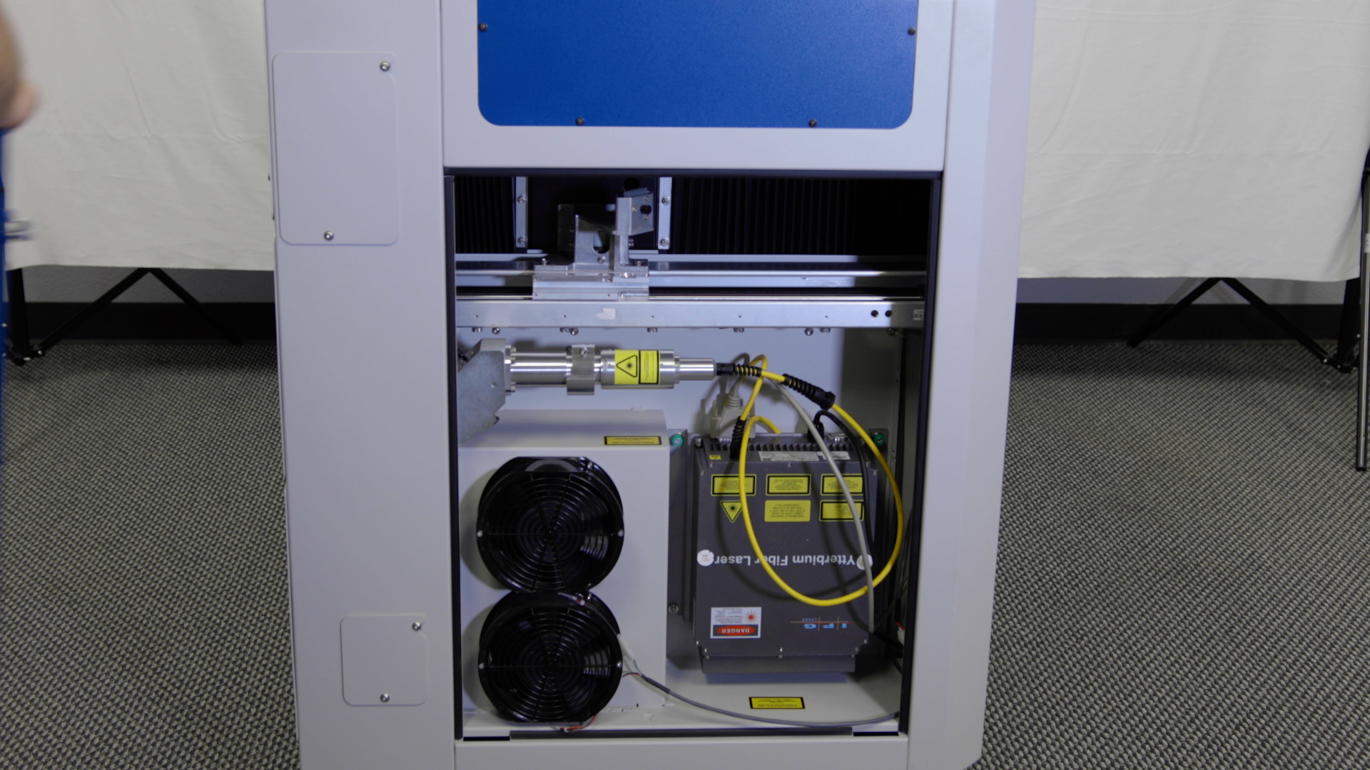
Using a 5/32” Allen Key, remove the left side panel from the machine.
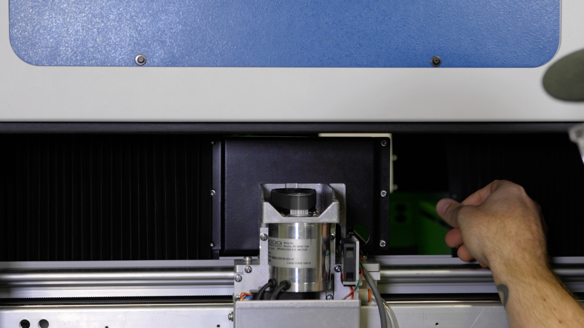
Manually move the x-axis assembly to the middle of the engraver.
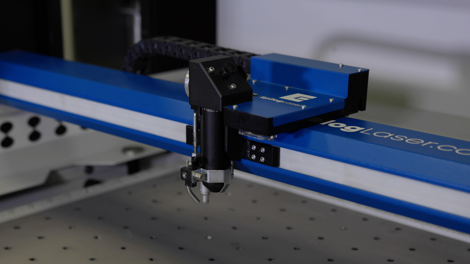
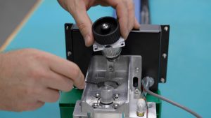
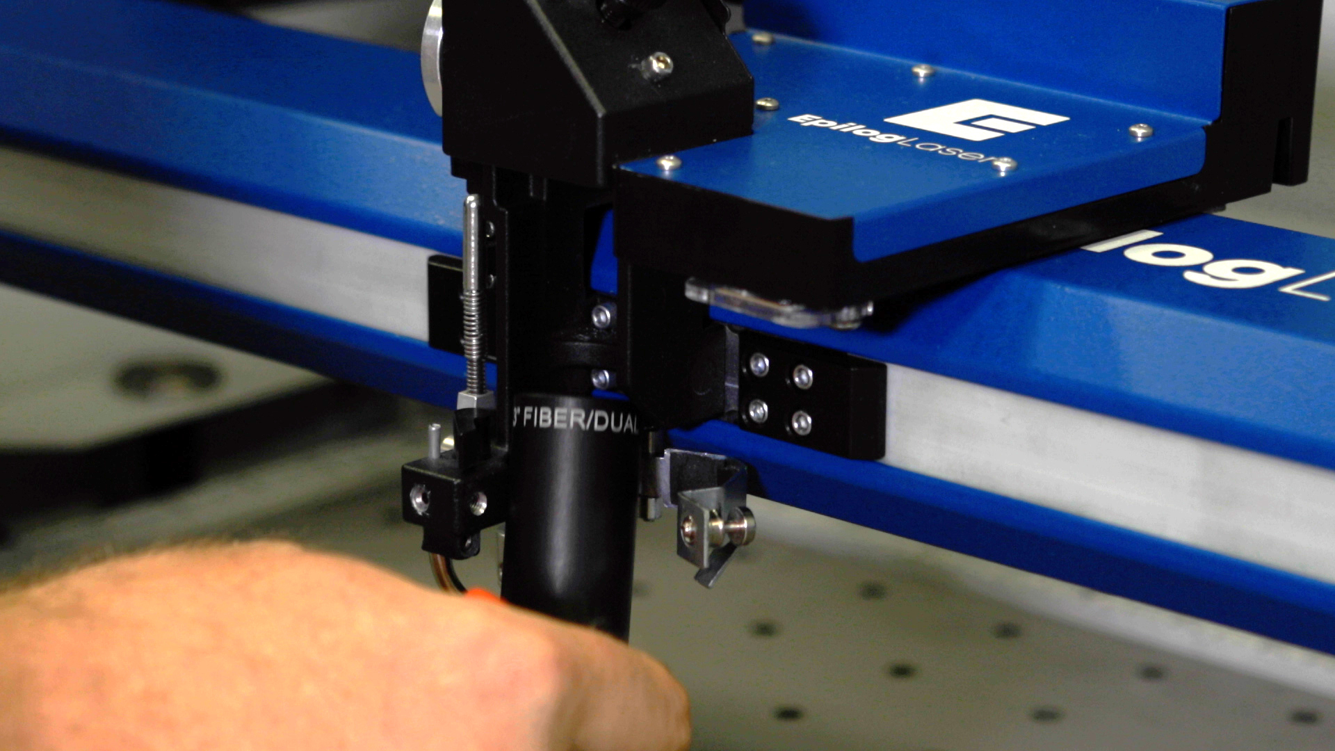
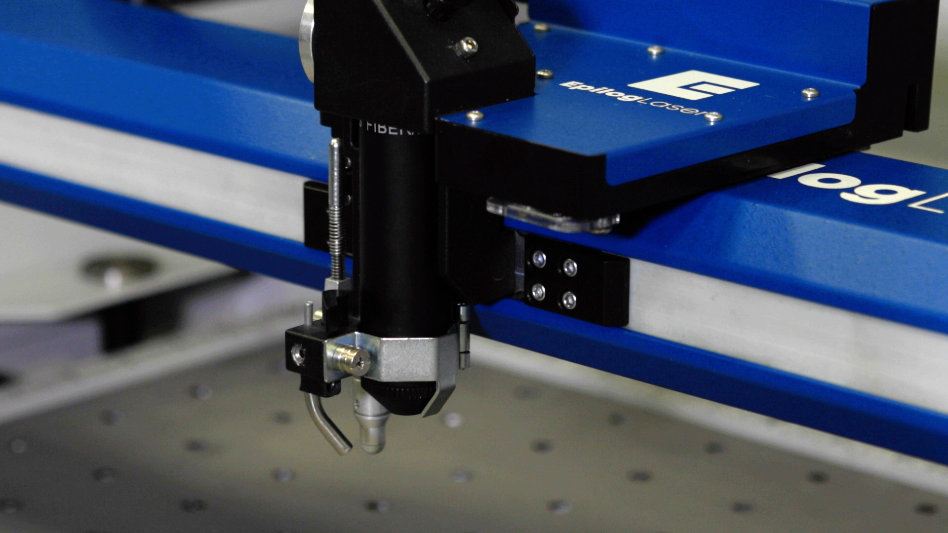
Remove the lens tube by using a Philips head screwdriver to unscrew the captive screw securing the front lens clamp.
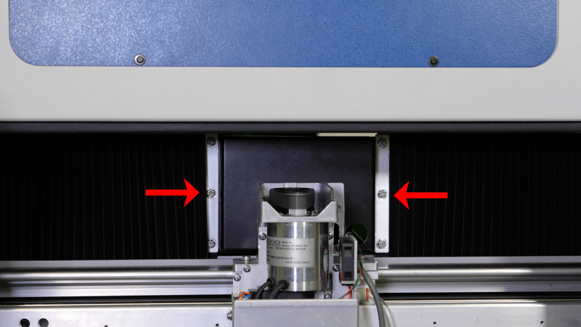
Remove the left and right bellows on both sides of the machine by loosening the six (6) 5/16” nuts which secure them in place.
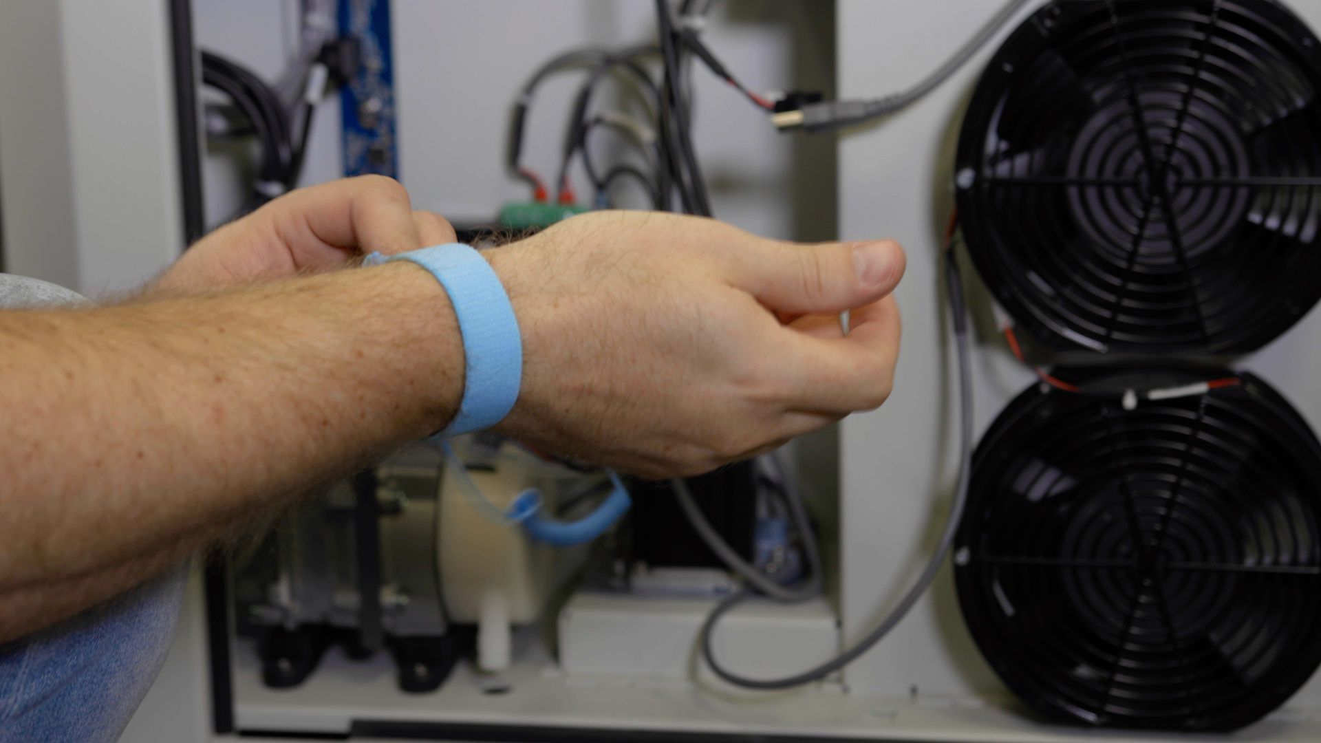
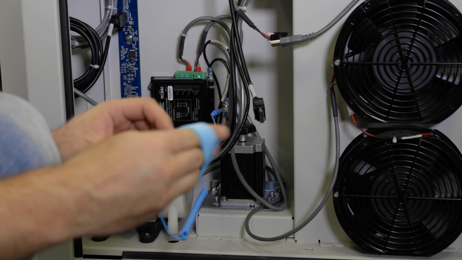
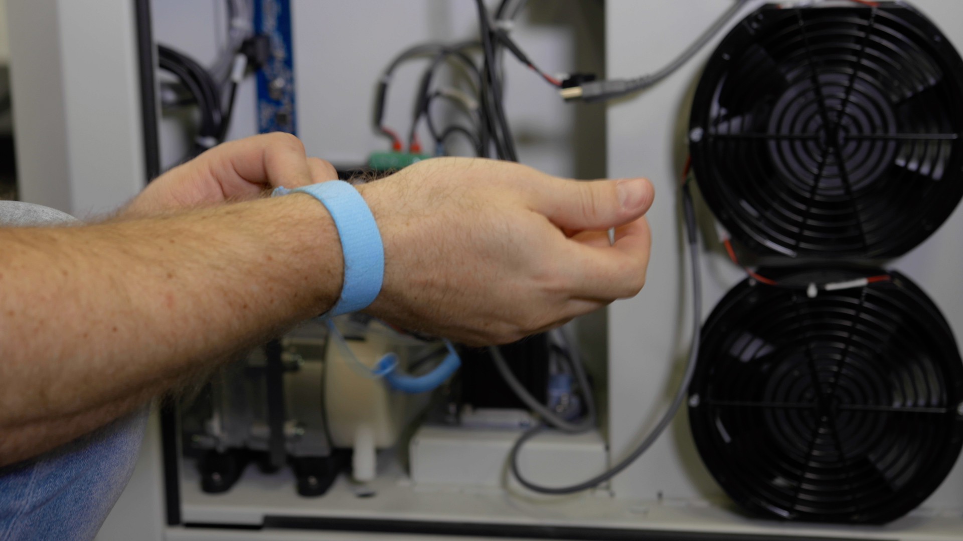
Put on the anti-static wrist strap. Clip the strap on to any metal part of the machine. Always wear the anti-static strap to avoid damaging the unit through static discharge.
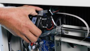
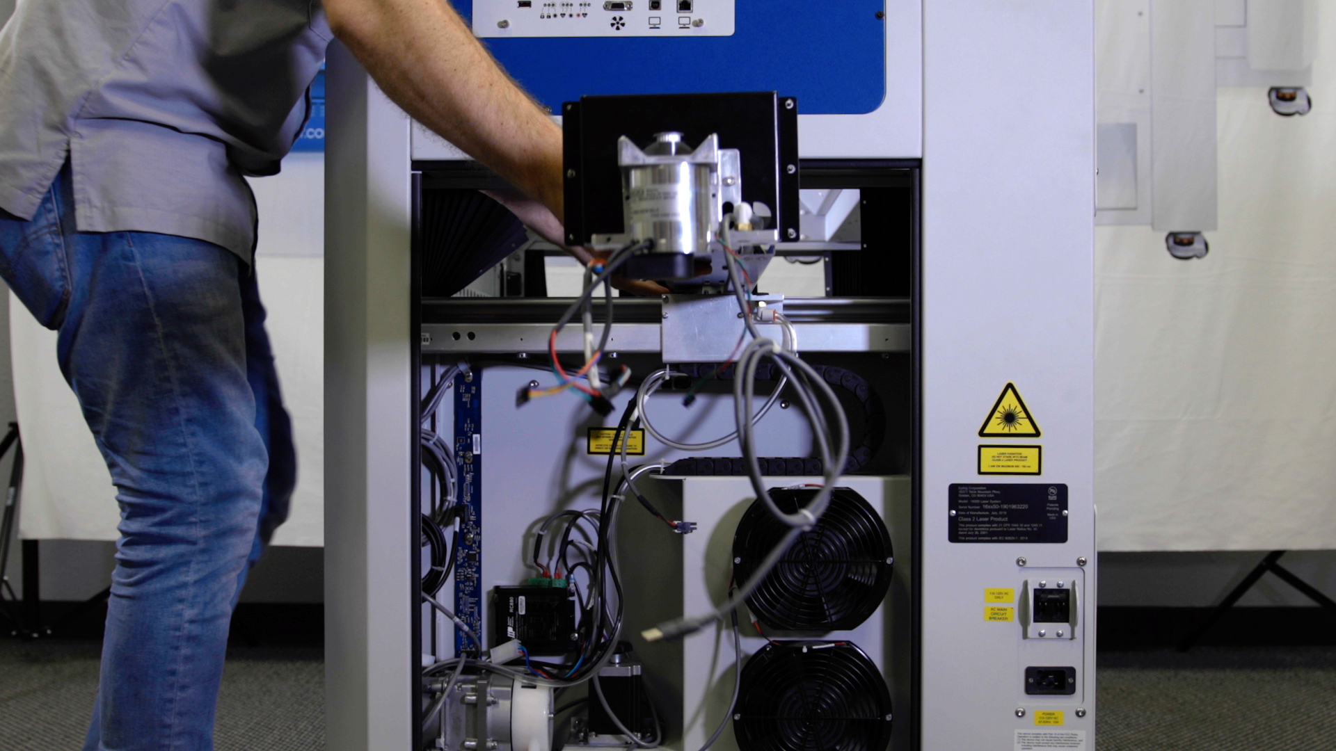
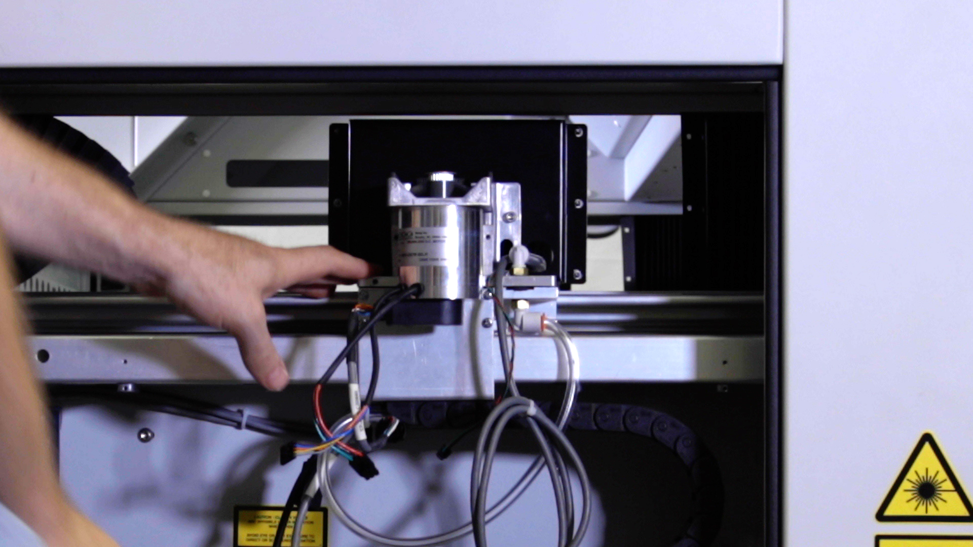
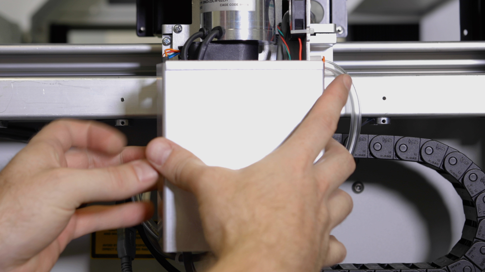
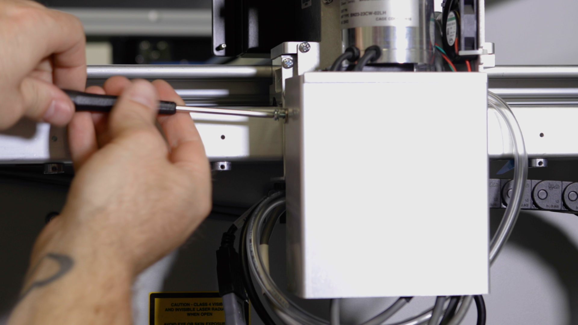
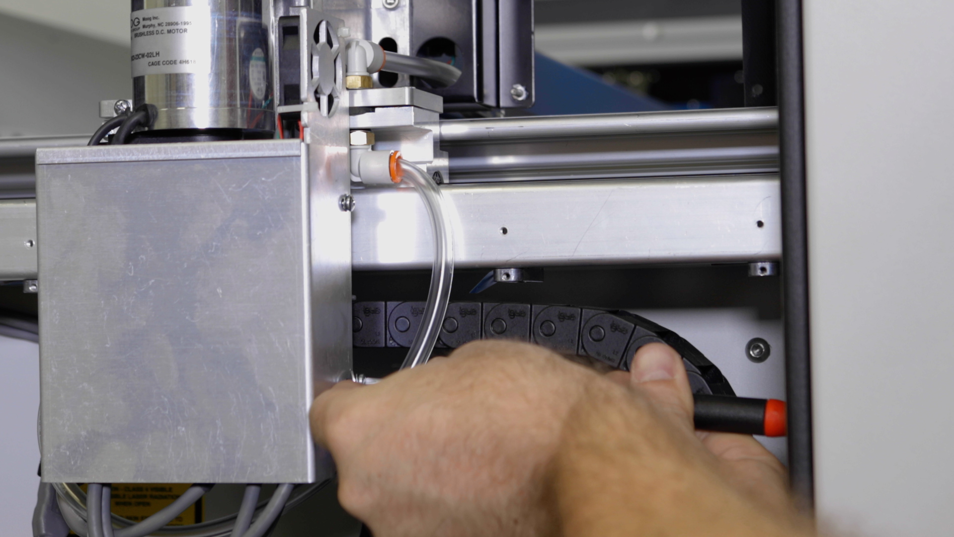
Using a Phillips screwdriver, remove the 4 screws that secure the x-axis motor drive board cover and set the cover to the side.
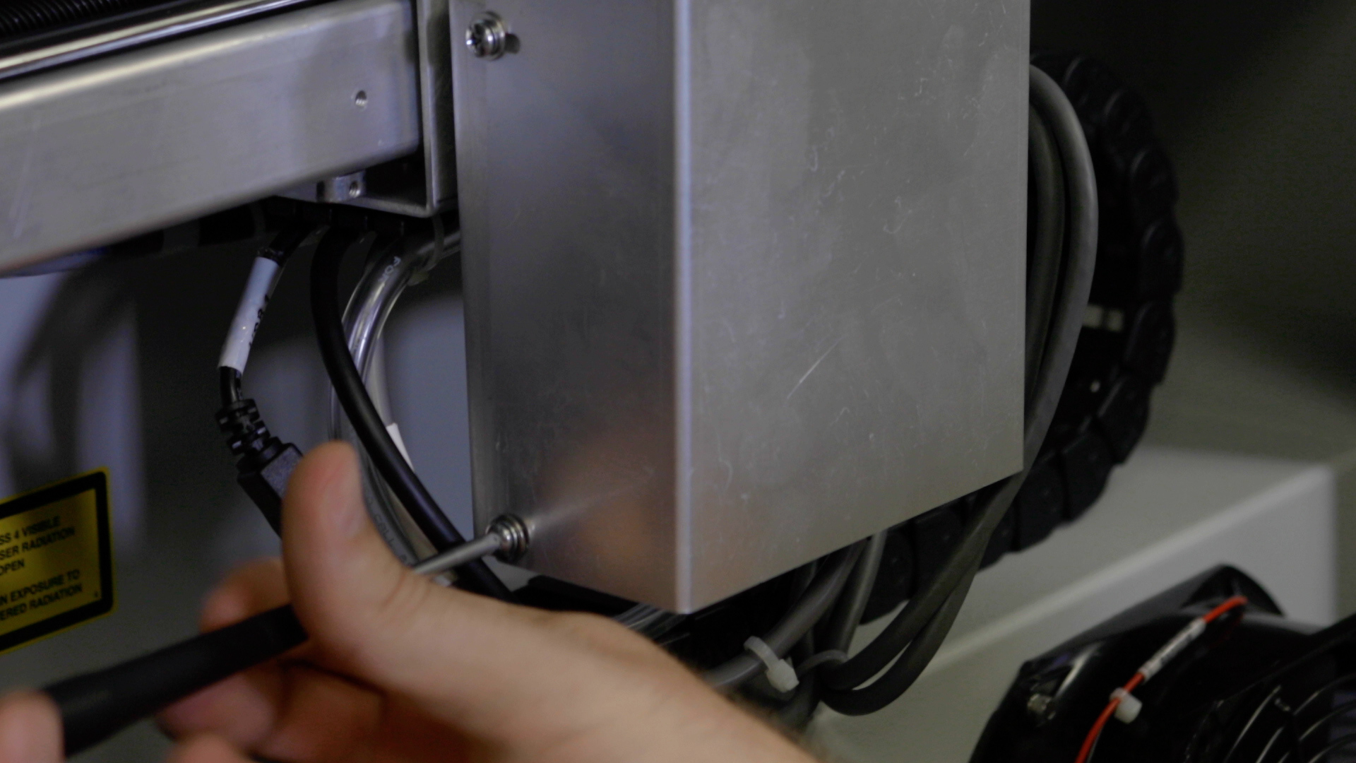
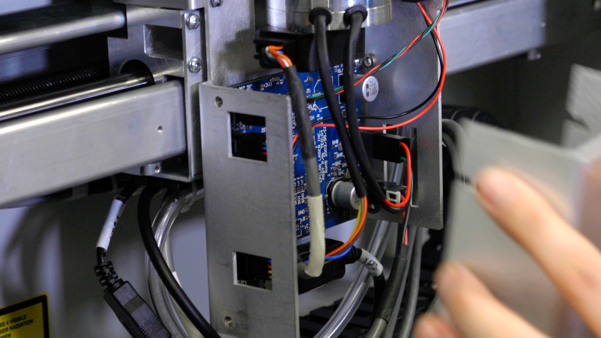
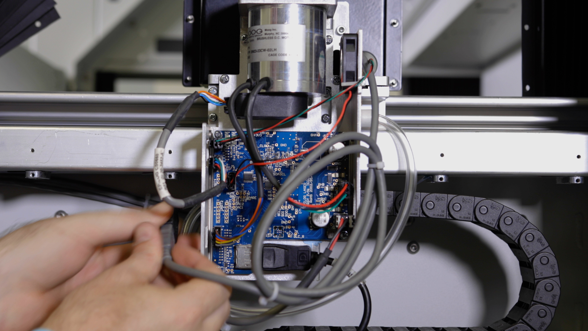
Now, disconnect the 7 electrical connectors from the drive board and set the board to the side.
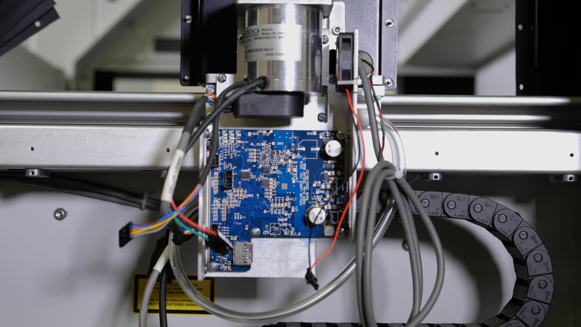
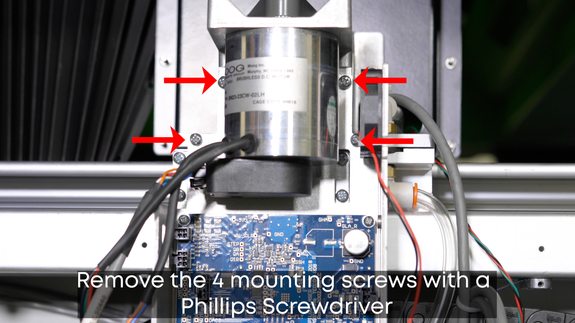
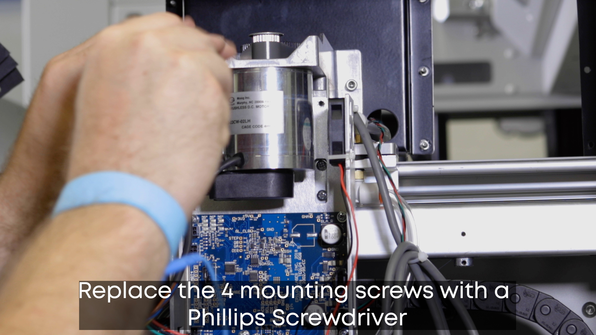
Remove the 4 mounting screws supporting the drive board using a Phillips Screwdriver.
Take off the anti-static wrist strap until needed when replacing the motor drive board.
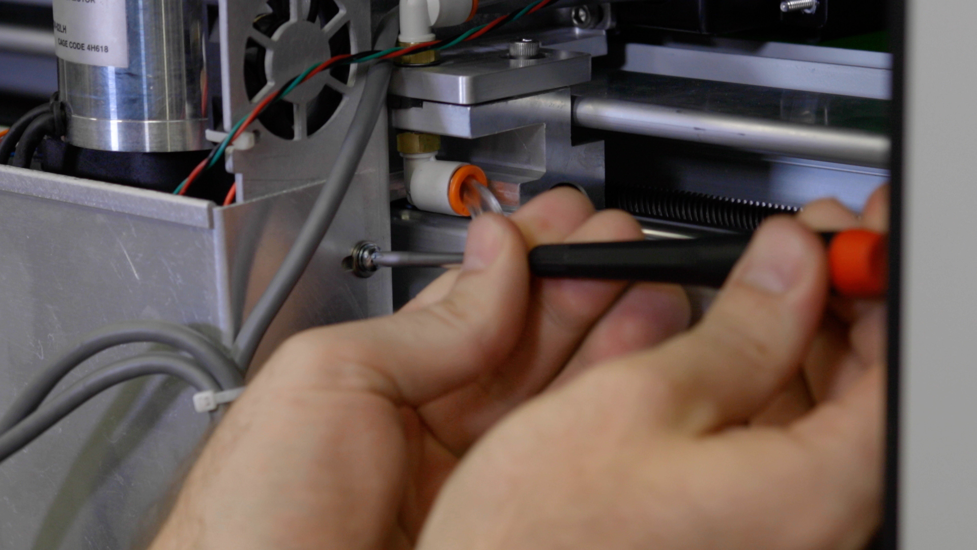
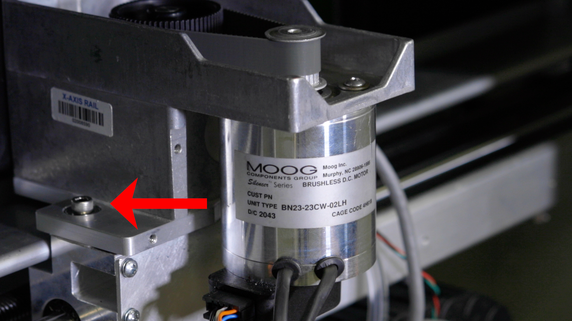
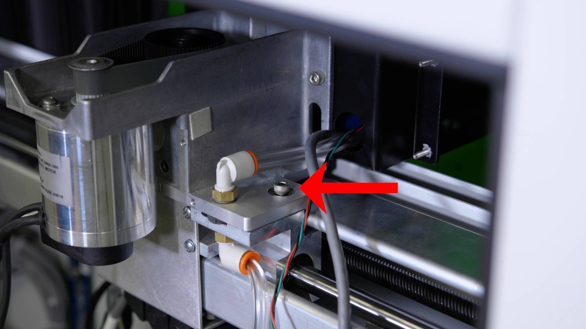
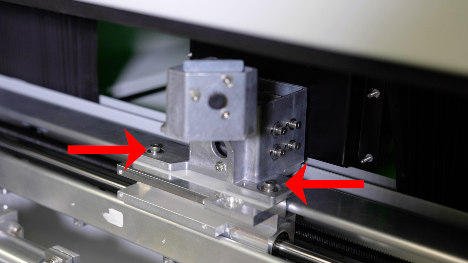
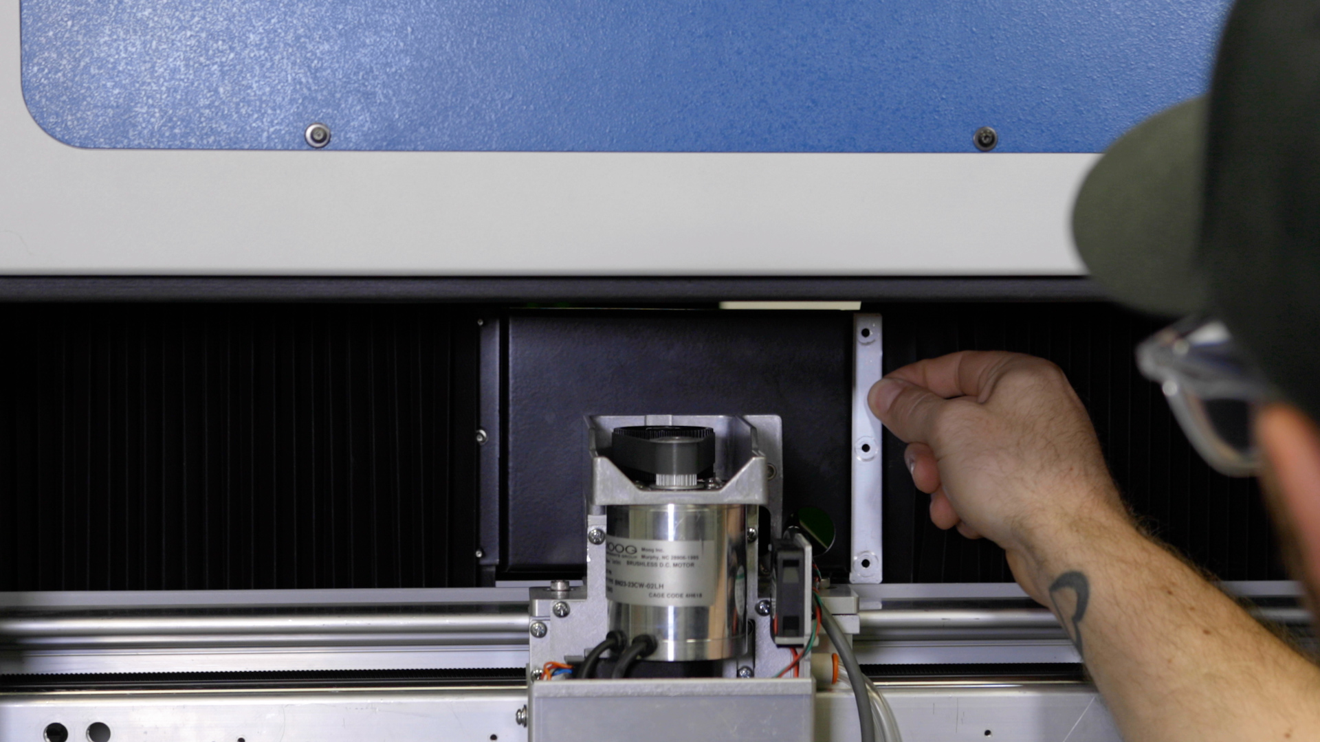
Remove the four 5/32” fasteners that secure the x-axis assembly to the y-axis bearings. There are two on the right side and two on the left side.

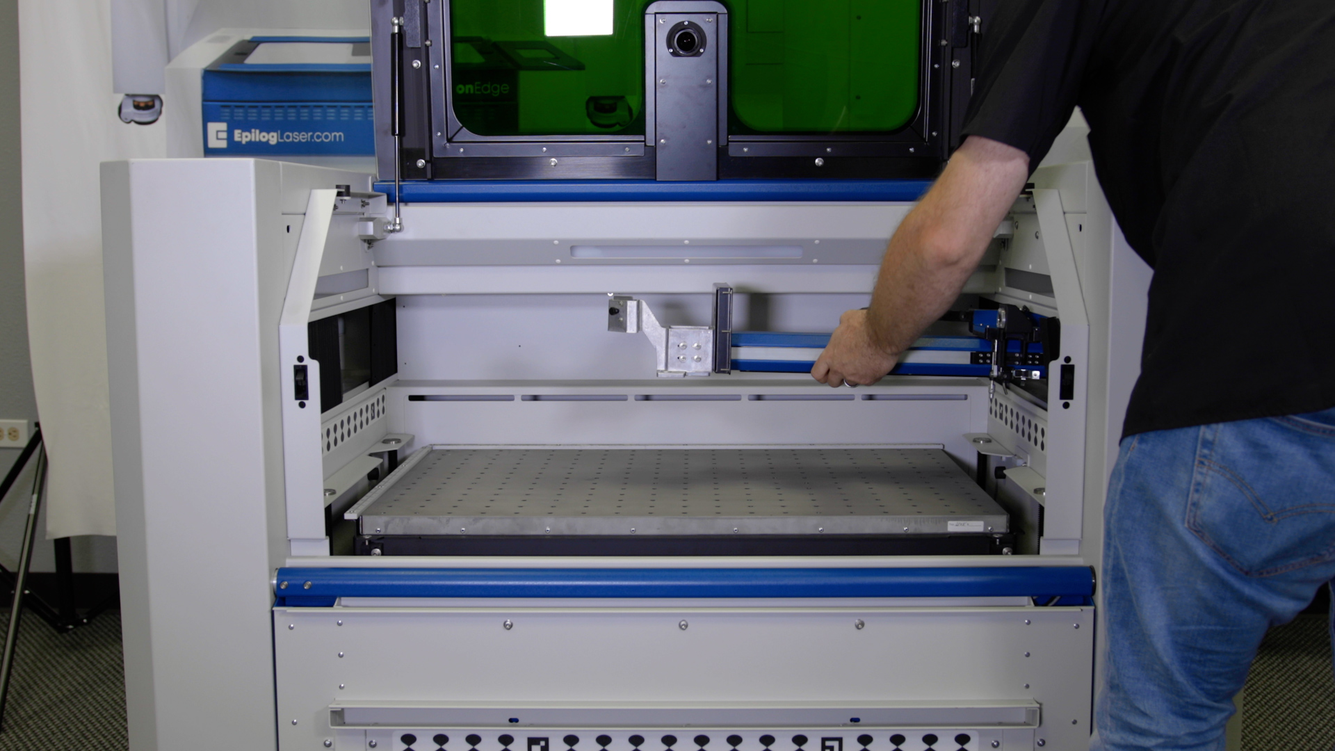
Slide the x-axis assembly out of the engraver through the right side of the machine, taking care to clear the carriage assembly through the opening without damage.
X-Axis Assembly Installation
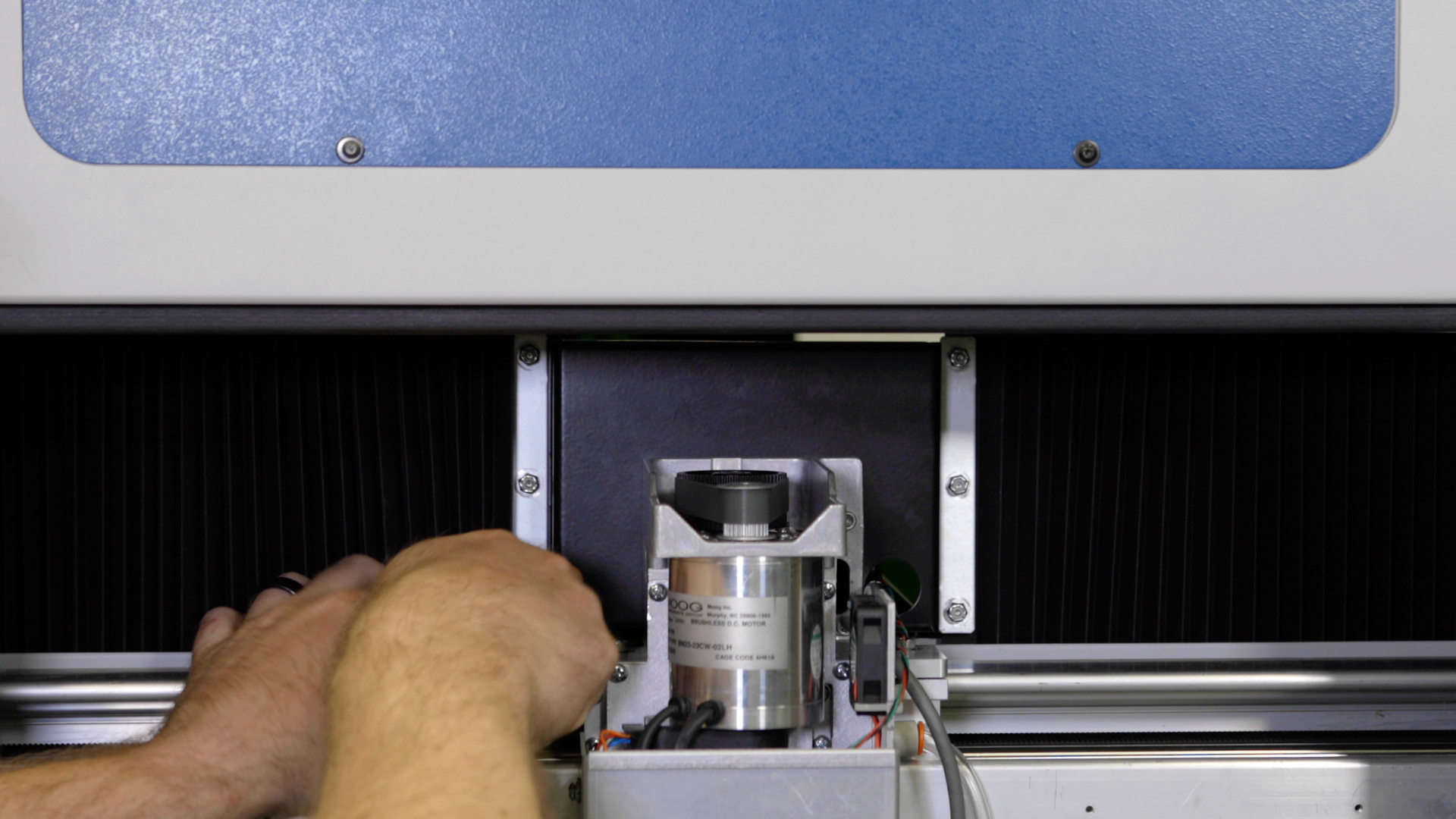
Insert the x-axis assembly through the right side of the engraver, taking care to clear the carriage assembly through the opening without damage.
Once fully inserted, place the x-axis assembly onto the y-axis bearing blocks. On the y-axis bearing blocks is a locating pin that ensures the correct placement on the x-axis assembly. These pins fit into an opening on both the left and right side of the x-axis assembly.
Install and/or tighten the four 5/32” fasteners that secure the x-axis assembly to the y-axis bearings. There are two on the right side and two on the left side.


Put on the anti-static wrist strap, clipping the strap to any metal part of the machine.
Replace the 4 mounting screws supporting the drive board with a Phillips Screwdriver.
Reconnect the seven (7) electrical connectors from the drive board. The electrical connectors on the drive board are all unique and as such, will only fit into one receptacle.
Replace the x-axis motor drive board cover and tighten the 4 screws securing it.
Reconnect the left and right bellows on both sides of the machine and tighten the six 5/16” nuts which secure them in place.
Install the lens tube by tightening the Phillips screw on the retaining collar which secures it, ensuring that it does not fall.
Replace both the left and right panels of the engraver.
Plug in and power on the machine.
After installation of a new x-axis assembly, confirm the home position is accurate and recalibrate it if needed.