This guide outlines the complete procedure for safely removing and installing the X-Axis assembly in a Fusion Pro laser system. Carefully follow each step to maintain alignment, prevent component damage, and ensure optimal system performance during reassembly.
Removal
-
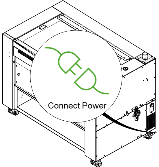
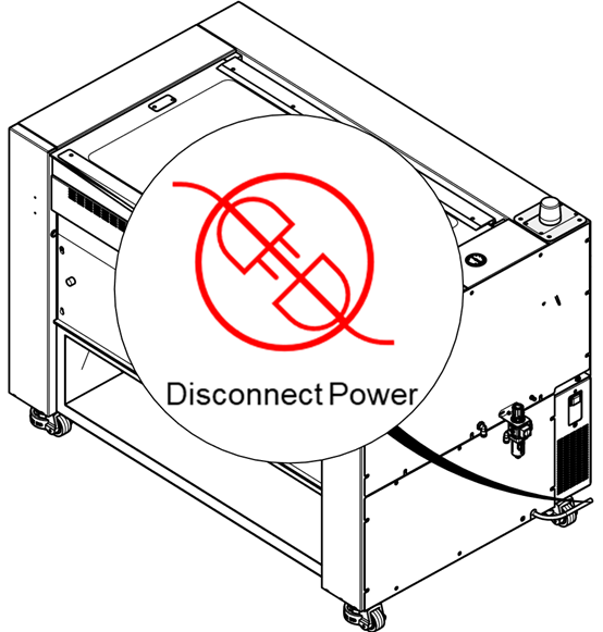
Power OFF the machine and disconnect the power cable.
-
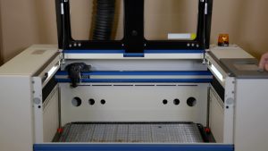
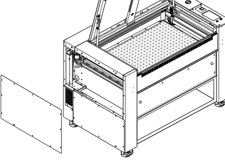
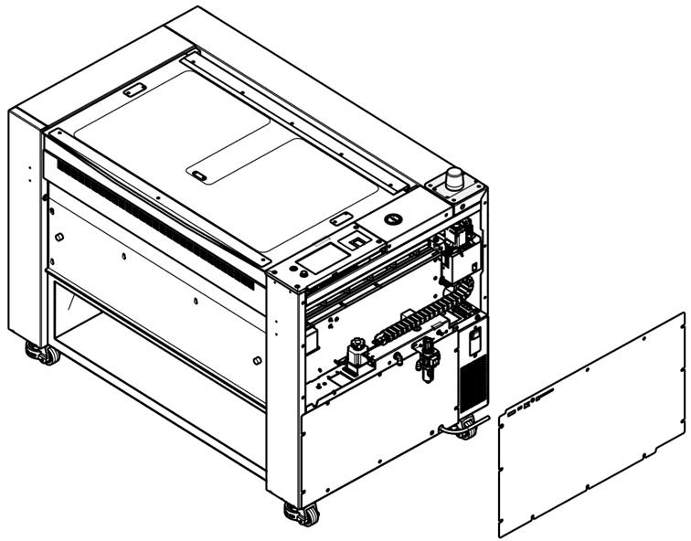
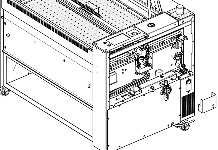
Remove the right and left side panels.
-
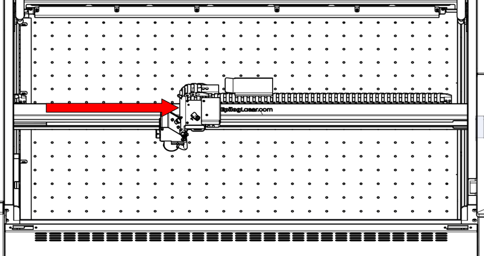
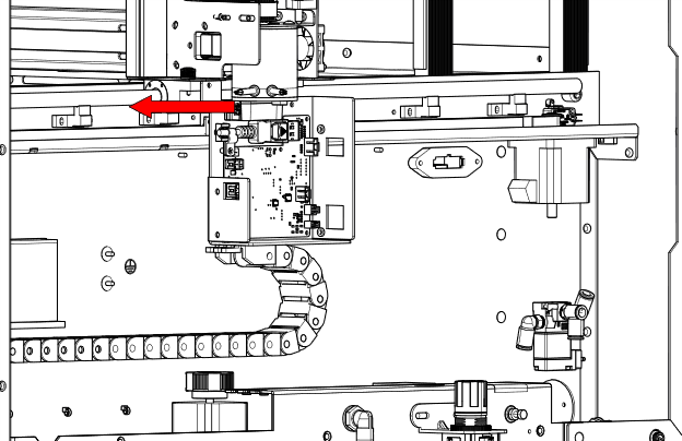
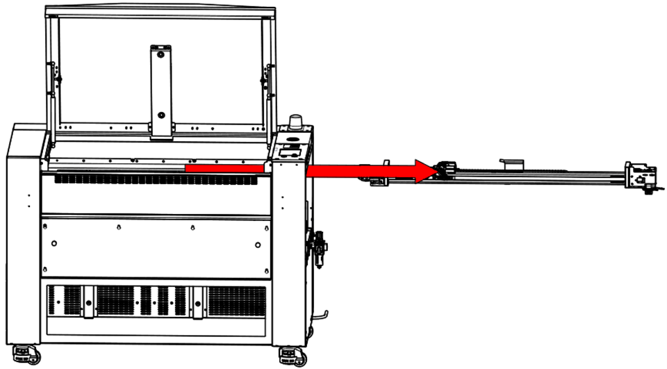
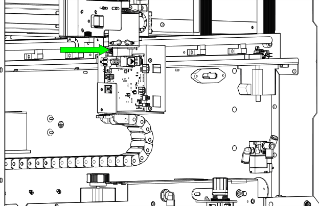
Move the X-Axis Rail to the middle of the machine.

-
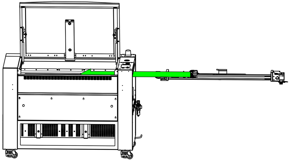
Move the lens carriage to the middle of the machine.
-
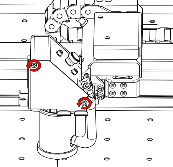
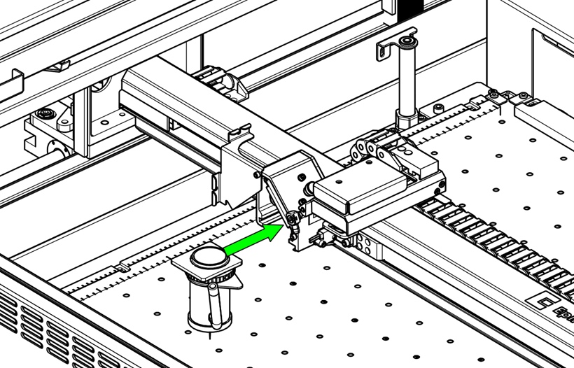
Loosen the thumb screws and open the carriage mirror cover.
-
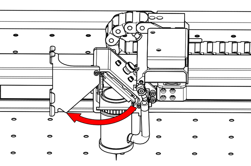
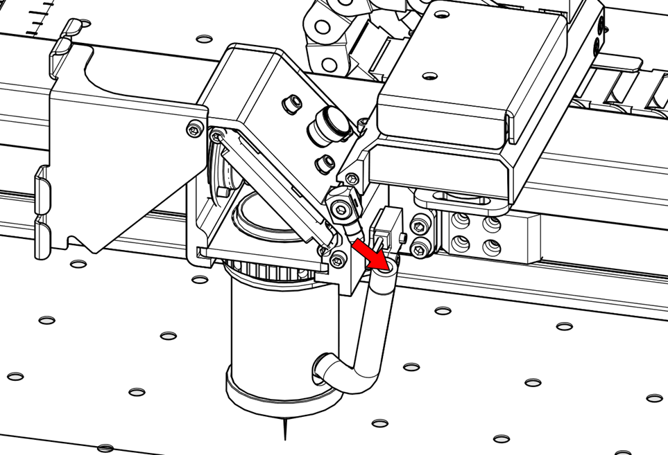
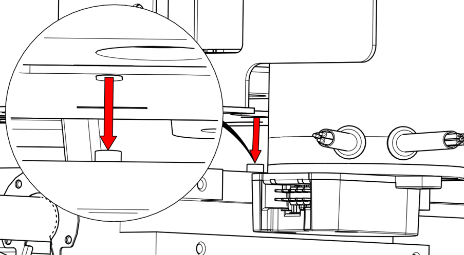
Disconnect the air assist tubing.
-
Remove the lens.

-
Close the carriage mirror cover.

-
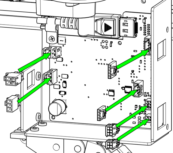
Remove the X-Axis drive board cover.
-
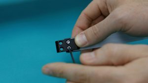
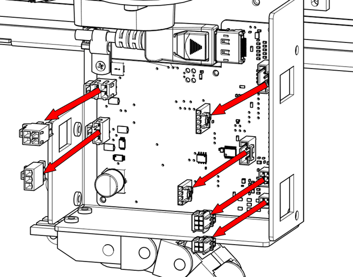
Disconnect the electrical harnesses from the X-Axis drive board and motor.
-
Disconnect the air assist tubing.

-
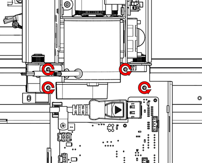
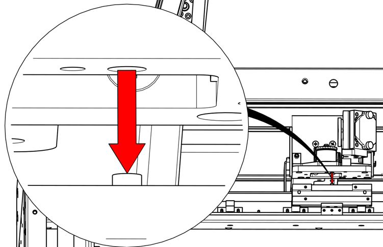
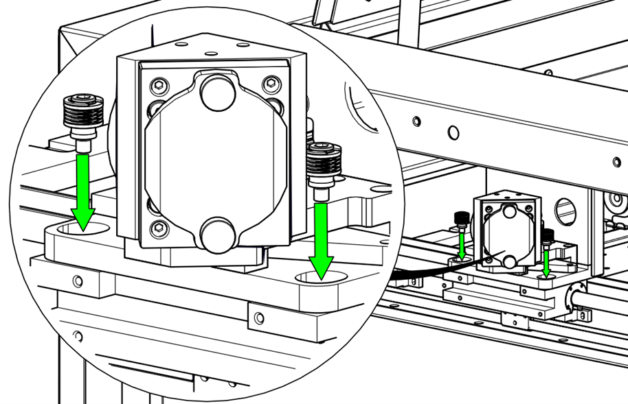
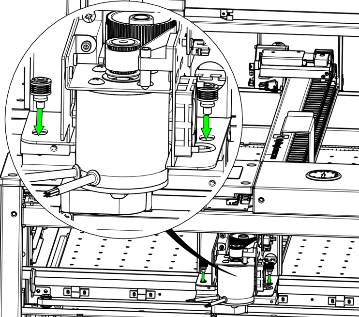
Remove the mounting screws on the X-Axis drive board mounting plate.
-
Remove the drive board and mounting plate.

-
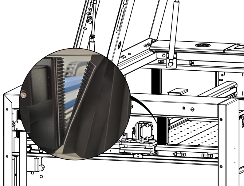
Disconnect the Velcro bellows from the X-Axis.
-
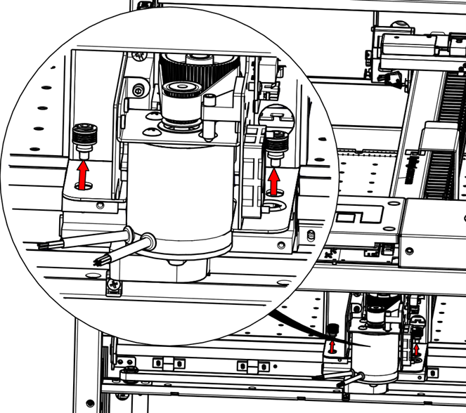
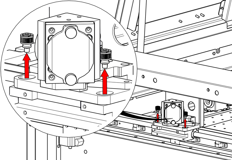
Remove the mounting hardware on both sides of the X-Axis.
-
Lift and remove the X-Axis assembly.
Installation
-
Install the X-Axis assembly.
-
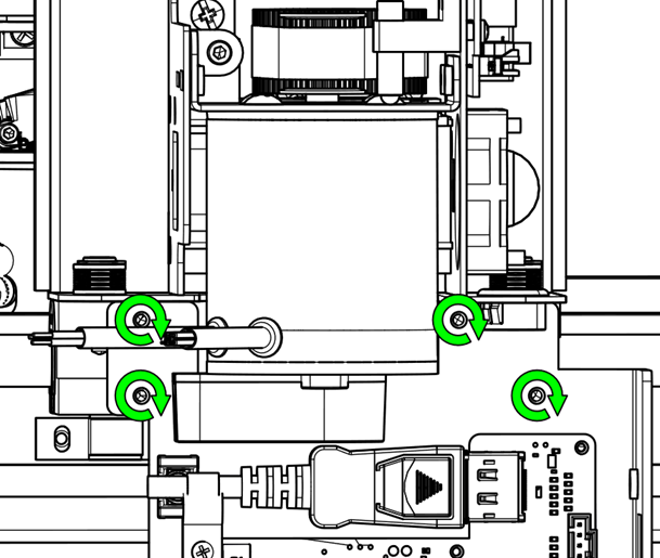
Align the X-Axis with the alignment pins.
-
Install the X-Axis mounting hardware.
-
Connect the Velcro bellows.

-
Attach the X-Axis drive board mounting plate.
-
Reconnect the electrical harnesses to the X-Axis drive board and motor.
-
Attach the X-Axis drive board cover plate.
-
Install the right and left side panels.
-
Install the lens.
-
Reconnect the power cable.