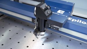
In this video we will walk you through replacing the X-axis belt on the Fusion Pro.
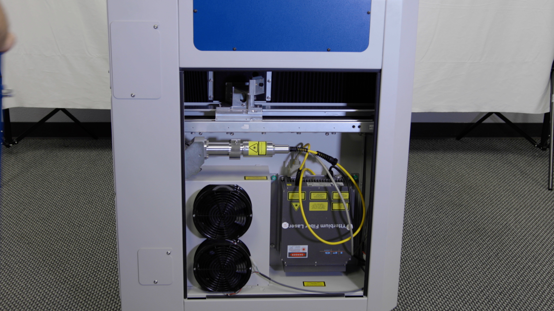
For this video we removed the X-axis assembly from the machine for filming purposes, but removing it is completely optional to complete this procedure.
Loosen X-Belt
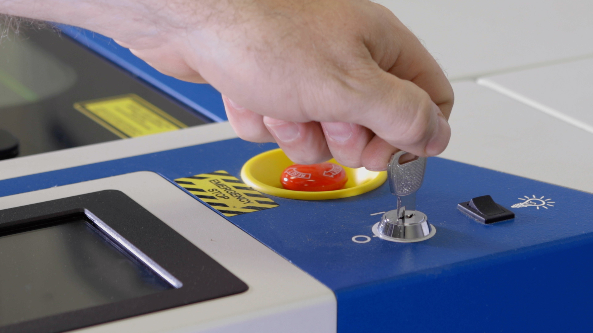
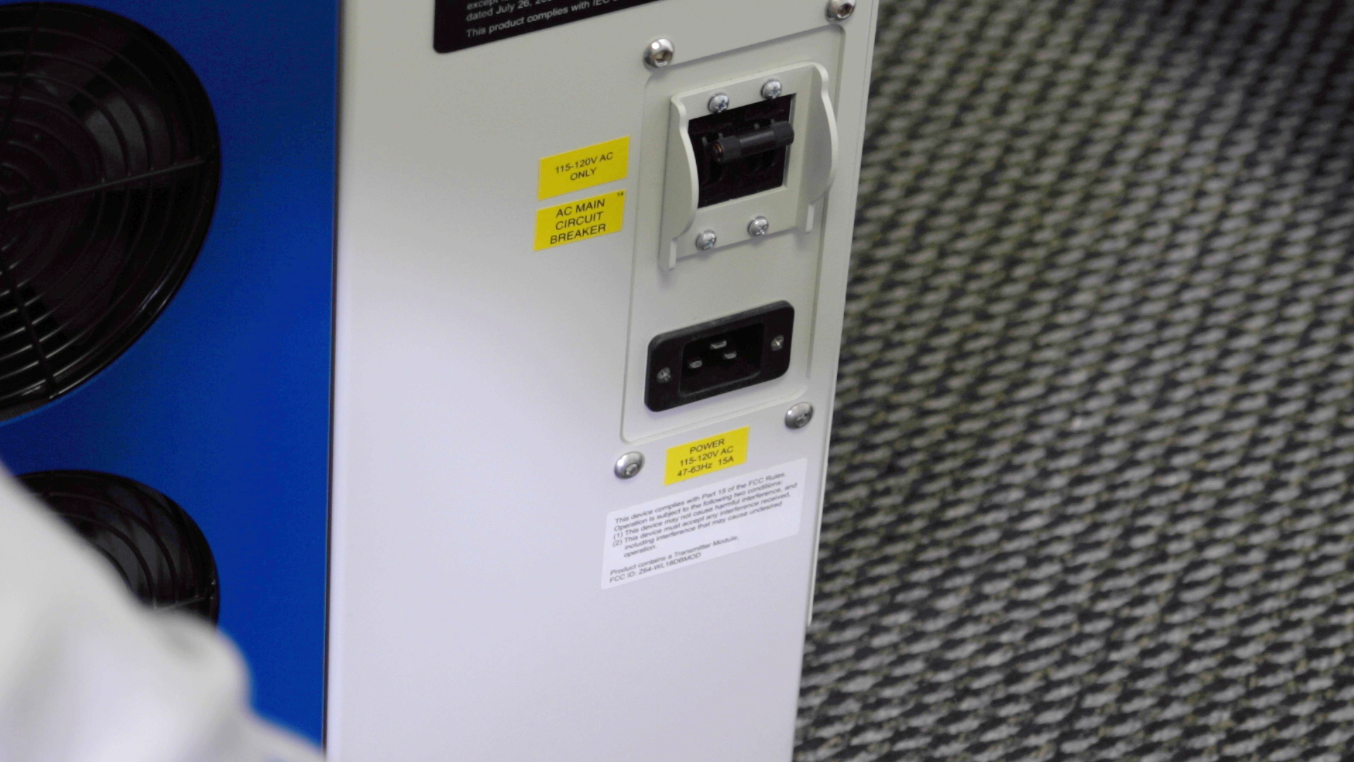
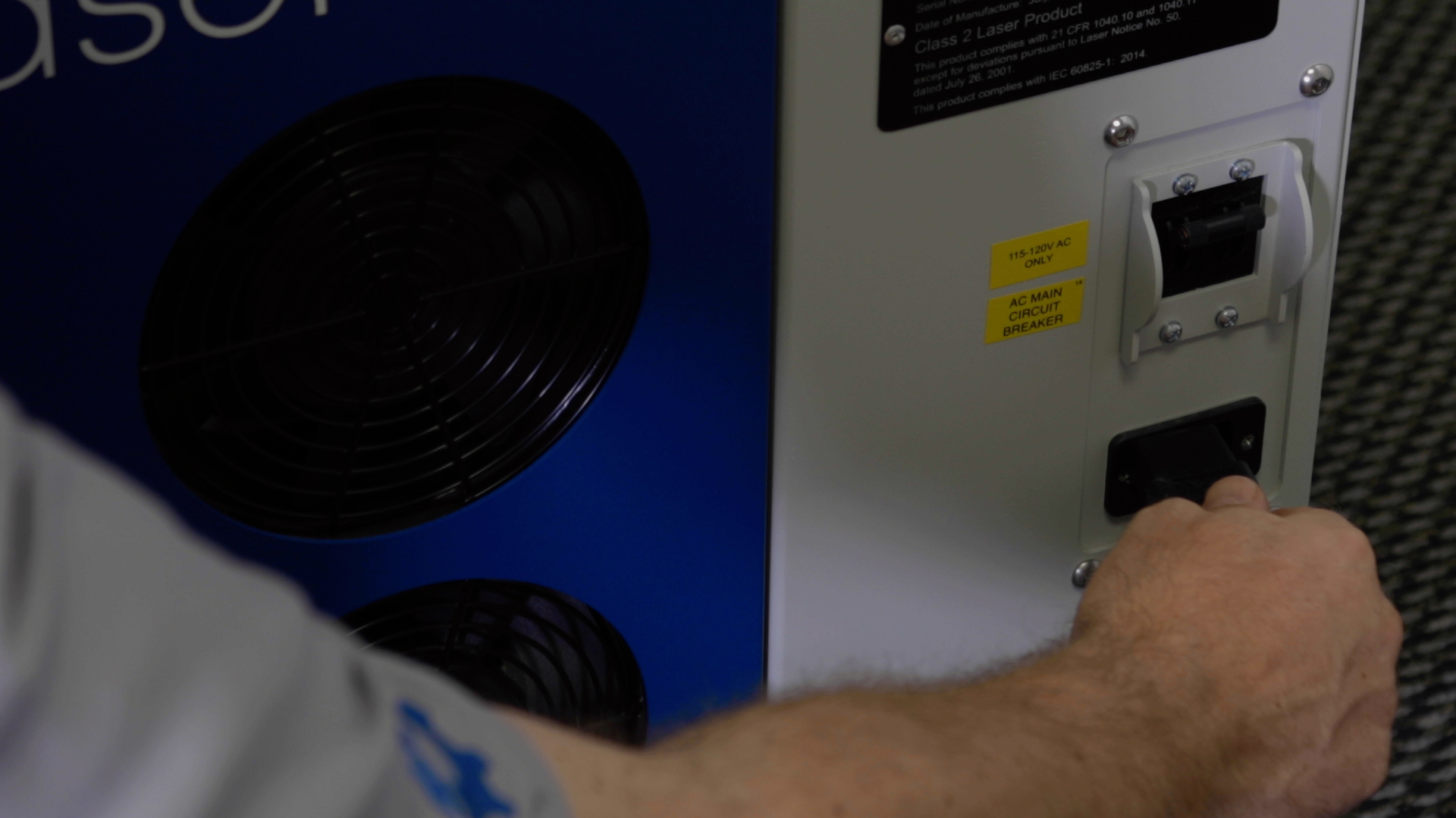
Start by powering of and unplugging the machine.
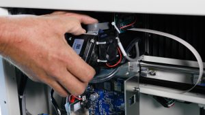
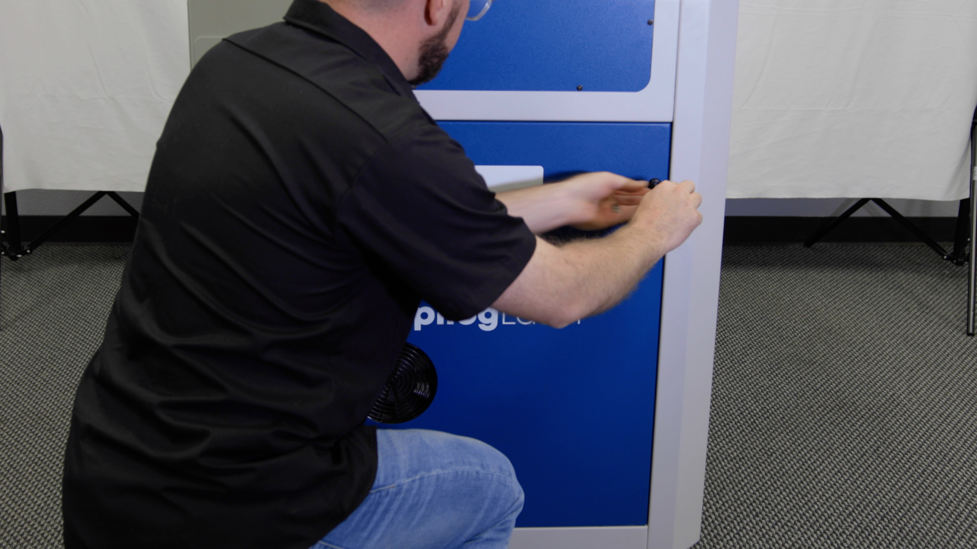
Using a 5/32” Allen Key, remove the left side panel from the machine.
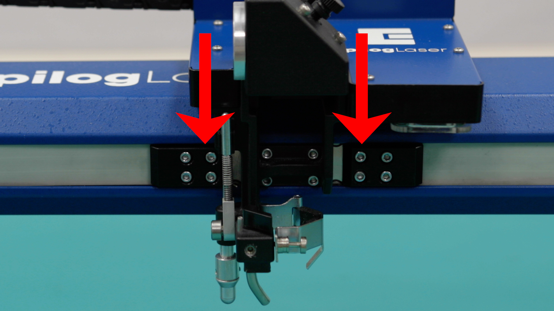
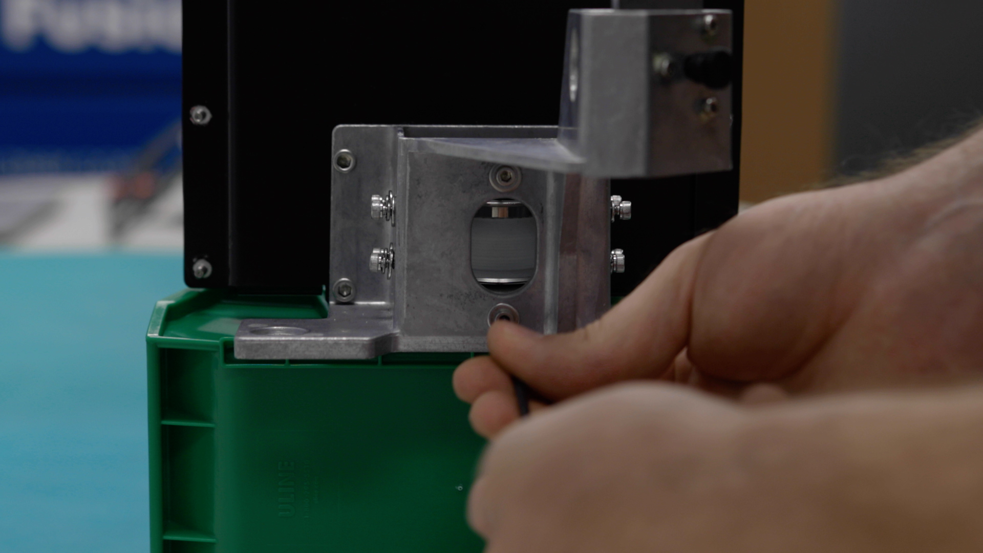
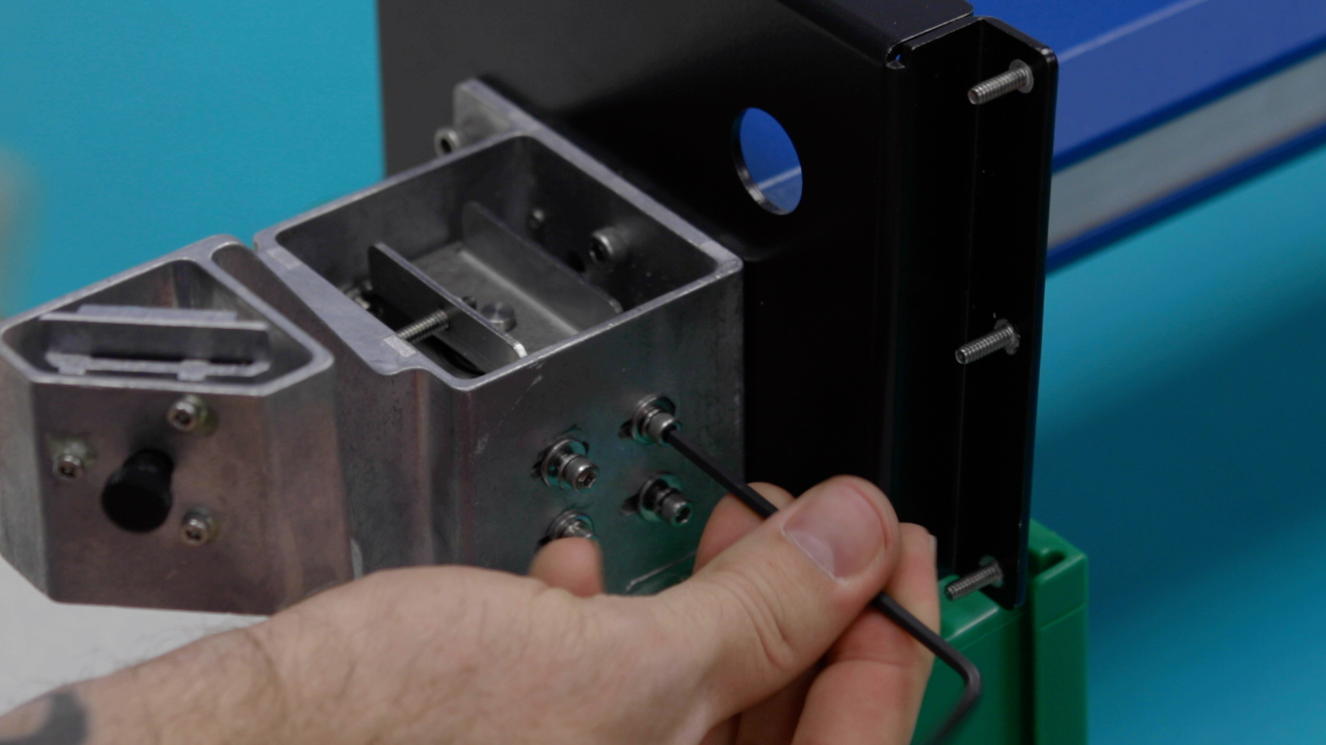
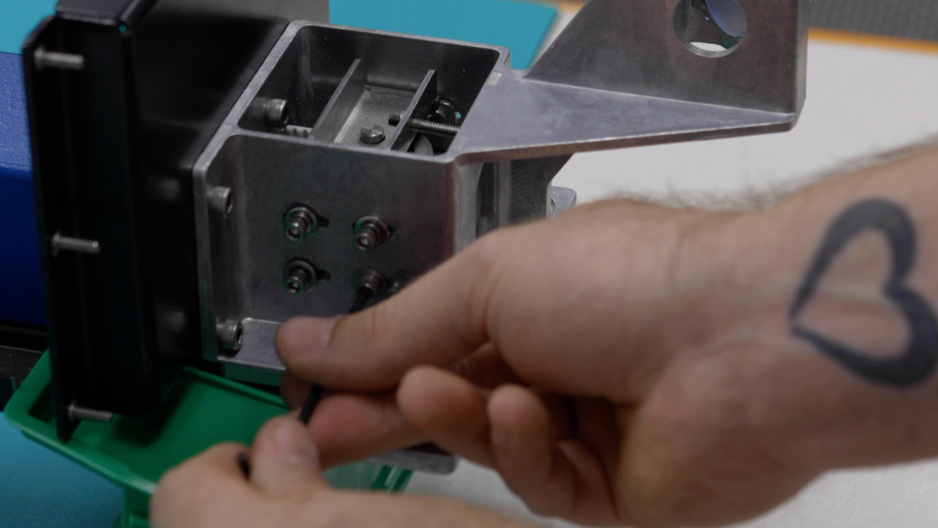
At the left side of the engraver, loosen the four idler mounting screws located on the front side of the x-axis assembly, and the four idler mounting screws located on the rear of the x-axis assembly.
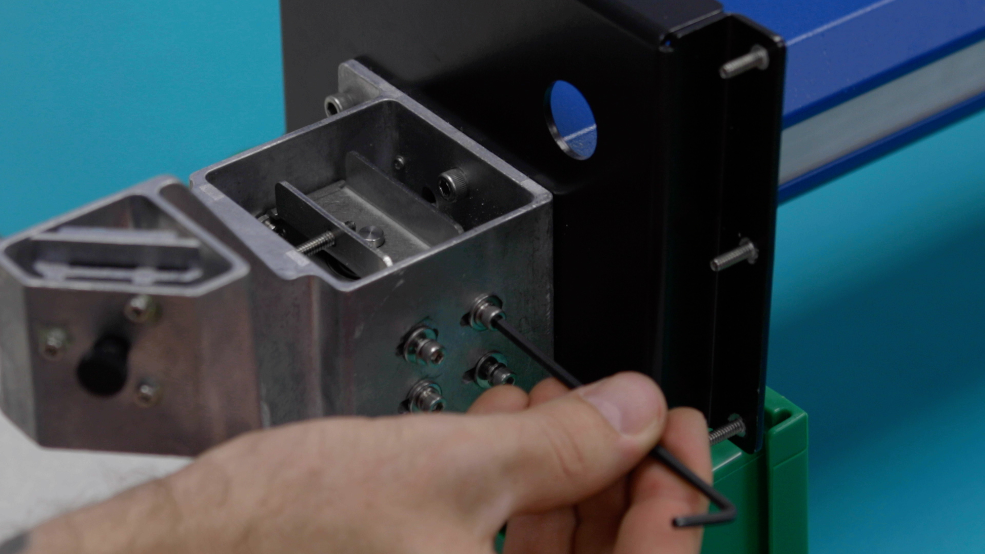
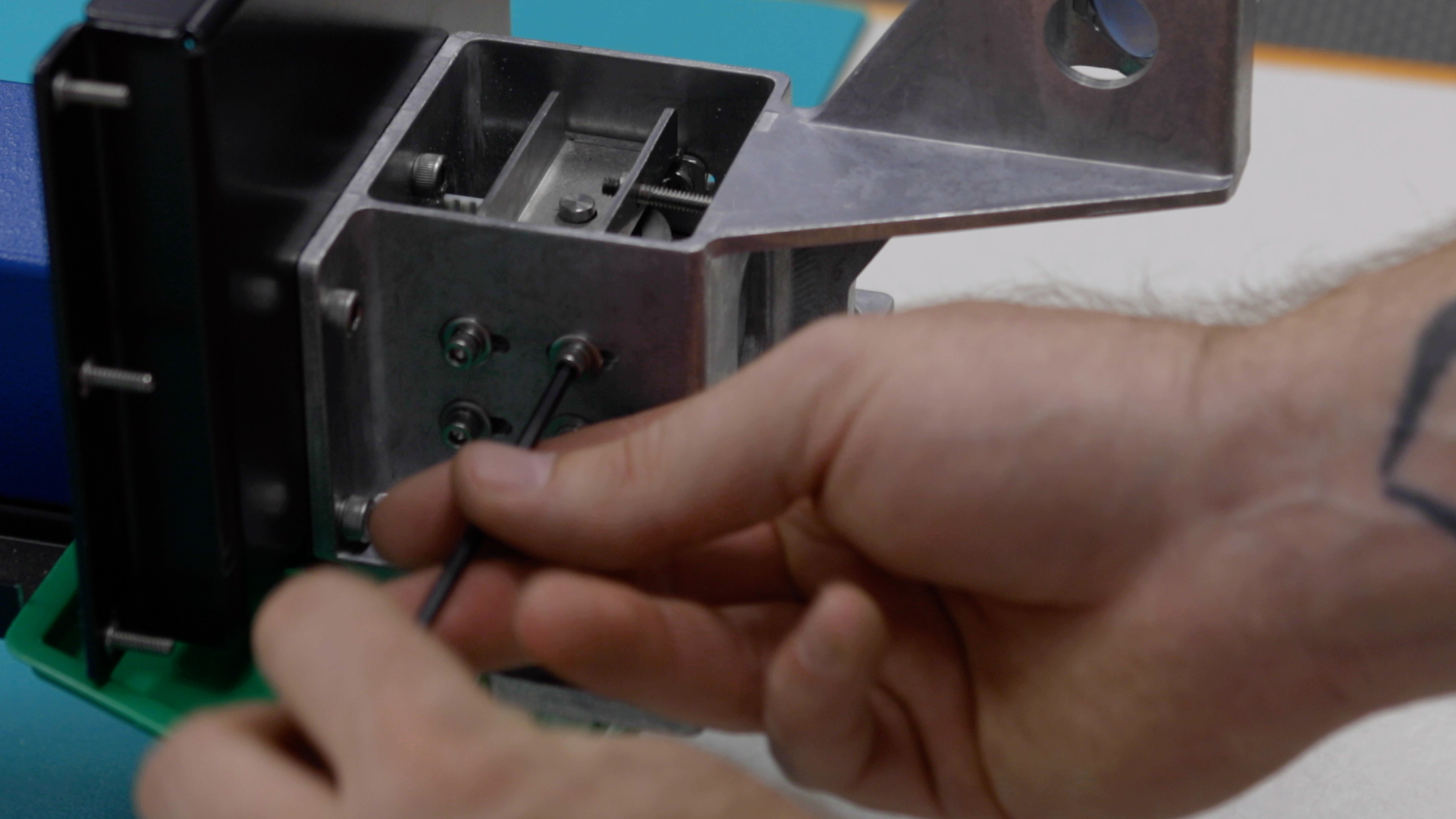
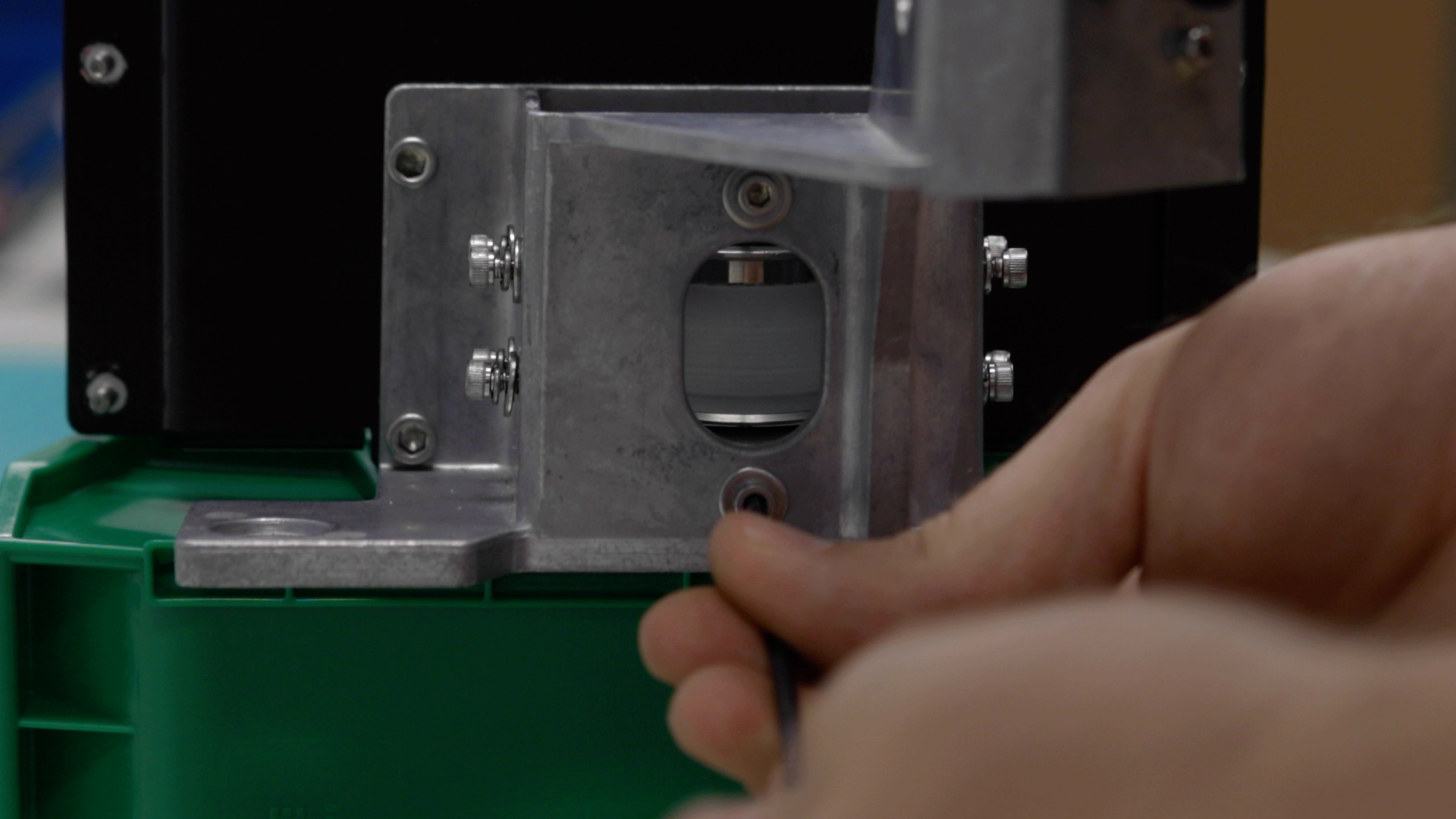
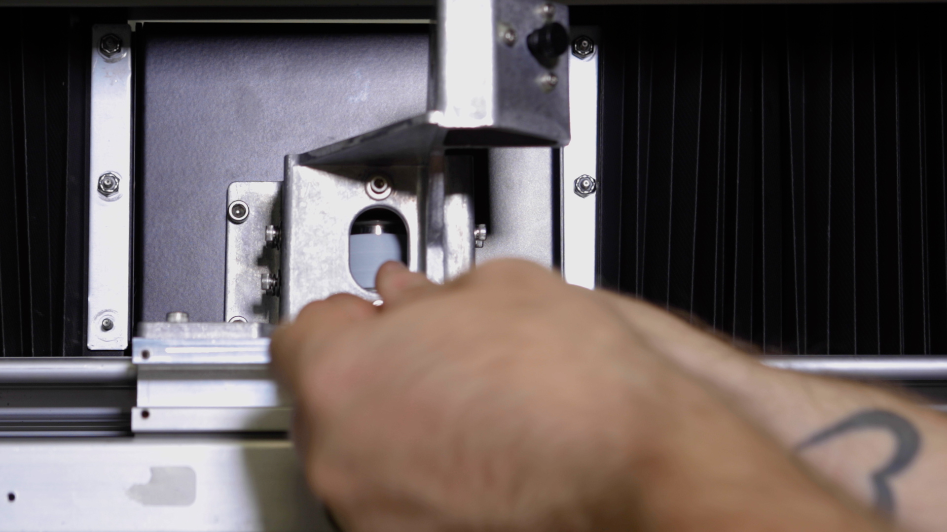
Remove the tension from the x-axis belt by loosening the two 7/64” screws on the idler assembly body.
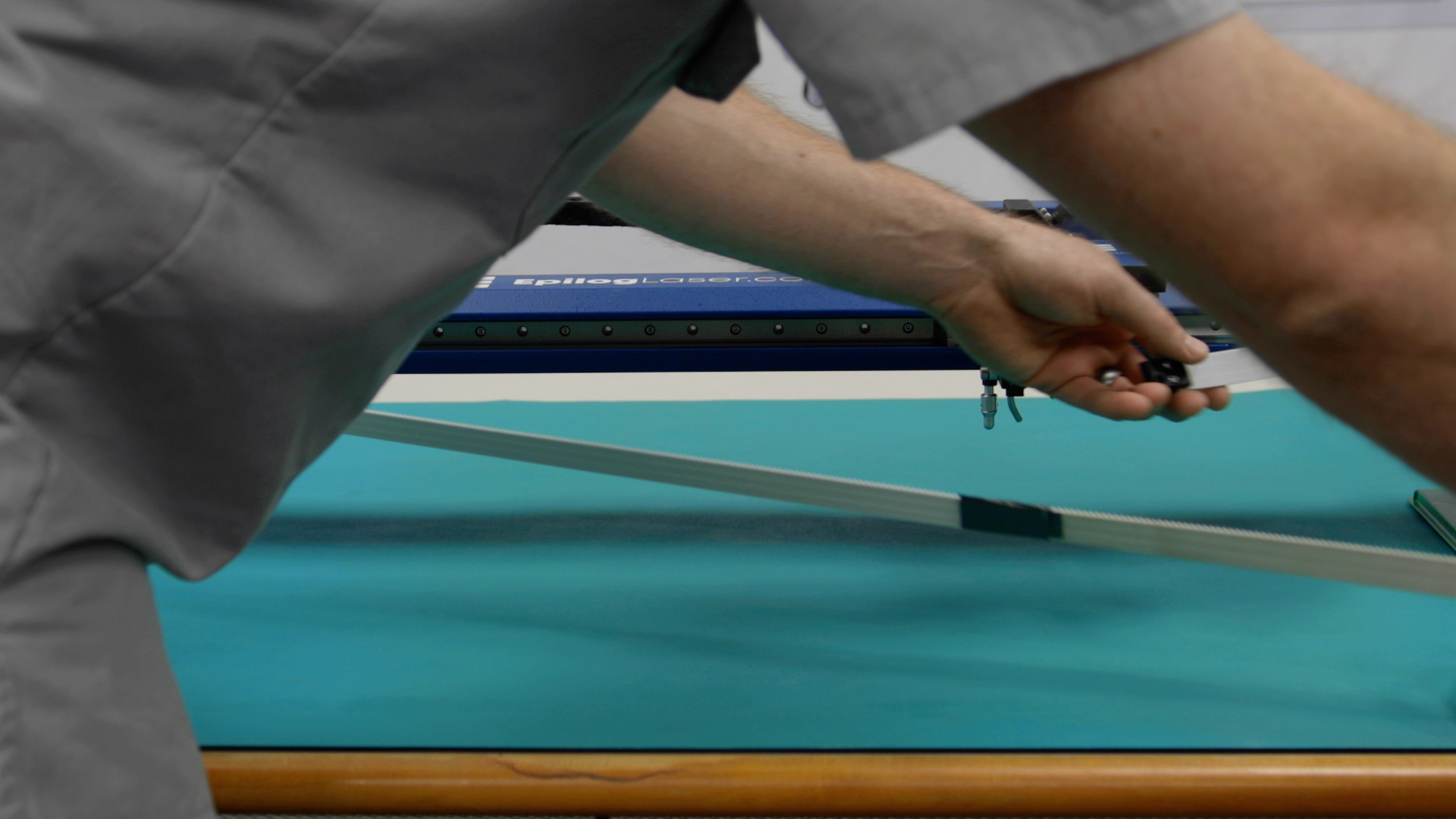
Now it’s time to remove the Belt Clamps. Manually move the lens carriage to the right side of the machine.
Locate the x-axis belt clamps, just to the left and right side of the lens carriage assembly. Using a 3/32” Allen key, remove the four inner x-axis belt clamp mounting screws.
Connecting Old X-Belt to New X-Belt
Now we will connect the old belt to the new belt to ensure successful installation of the new X-axis belt.
Thoroughly clean the outer (smooth) side of the belt that is currently installed in the engraver.
Pull the right side of the belt away from the lens assembly and place it next to the new belt end-to-end.
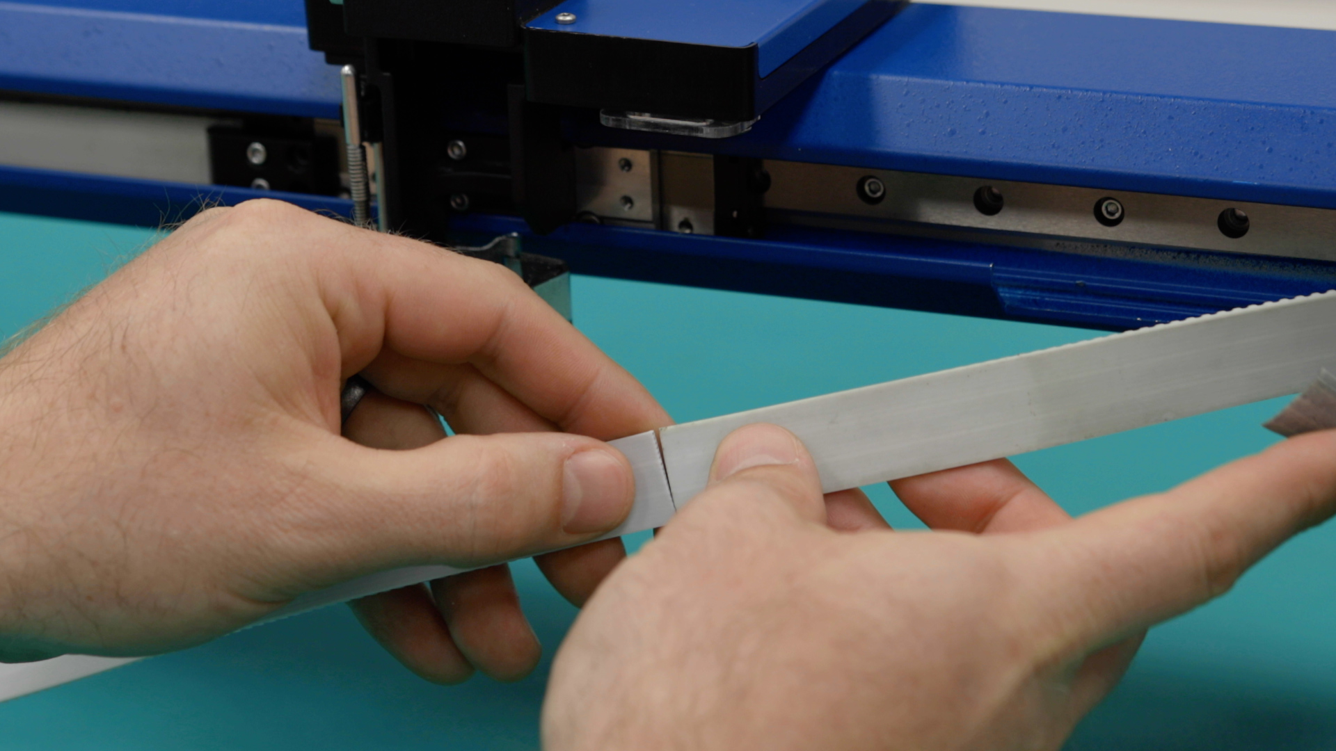
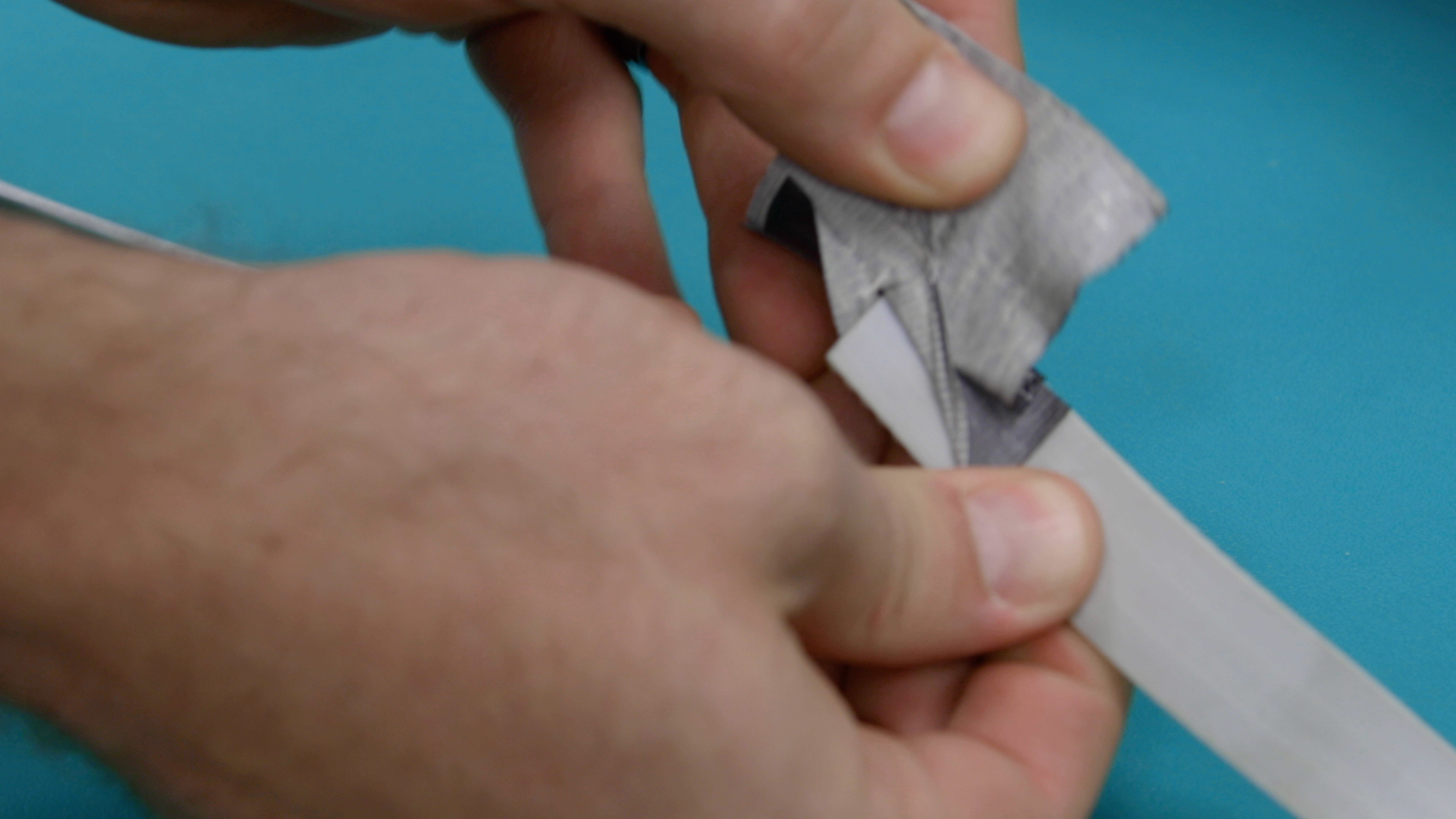
Using Duct Tape, or a similar, heavy-duty tape, join the old and new belts together by placing a strip of tape on the outer (smooth) sides.
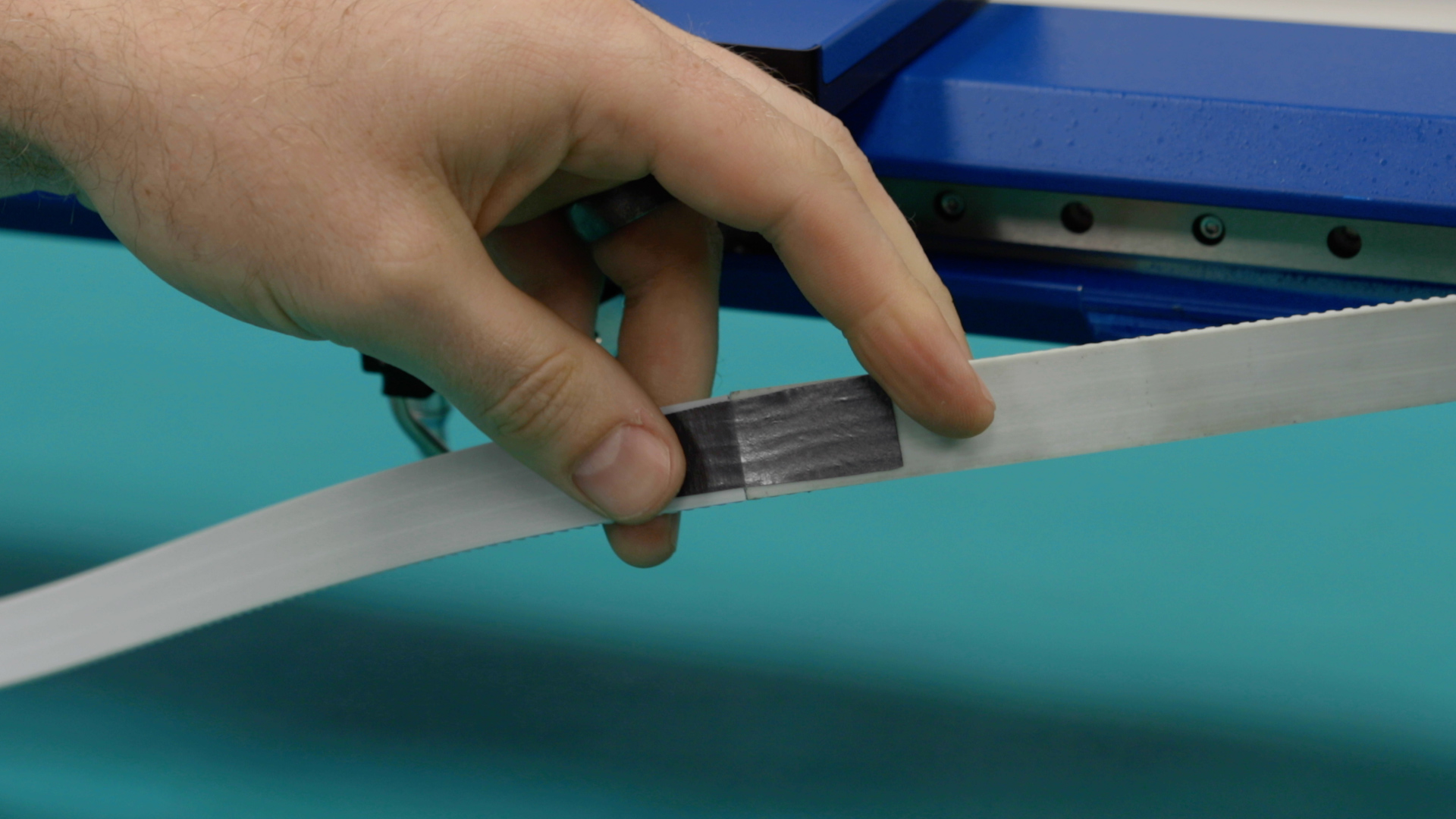
Before securing both the old and new belts together, ensure that the orientation of the teeth match. The teeth of the belt just face towards the rear of the engraver, while the smooth side should face the front of the engraver.
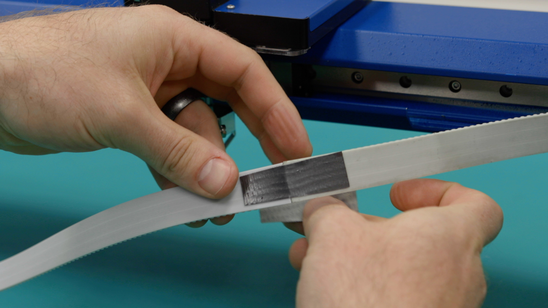
Place an additional piece of tape around the connection point of the new and old belts.
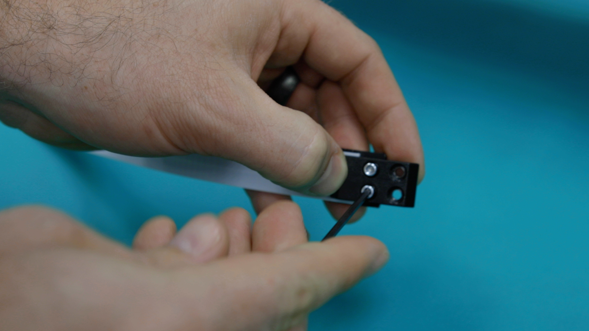
Once the new and old belts have been joined together, attach the right-side belt clamp to the untaped side of the new belt. This will prevent the new belt from being pulled into the reducer housing.
Ensure that the belt clamp is centered on the belt before tightening the clamp.
Replace Old X-Belt with New
Slowly pull on the left side of the old belt to remove it while subsequently threading the new belt through the x-axis assembly.
Once the connection point between the new and old belts has exited the idler assembly on the left side of the x-axis assembly, disconnect the belts by removing the tape.
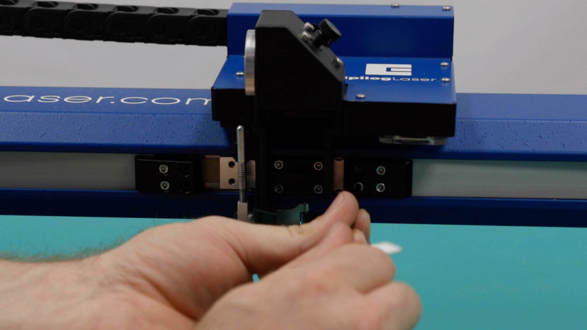
Install the belt clamps by connecting the remaining belt clamp to the left side of the x-axis belt, ensuring that it is centered on the belt before tightening the clamp.
Place the belt clamps in position. Install and tighten the four 3/32” inner x-axis belt clamp mounting screws.
Tension New X-Belt
Now it’s time to tension the X-axis belt. Begin to apply tension to the X-axis belt via the two 7/64” x-axis belt tensioning screws that were loosened earlier until there is no slack left on the belt.
Once the slack is removed, you will need to run an engraving test.
Engraving Test
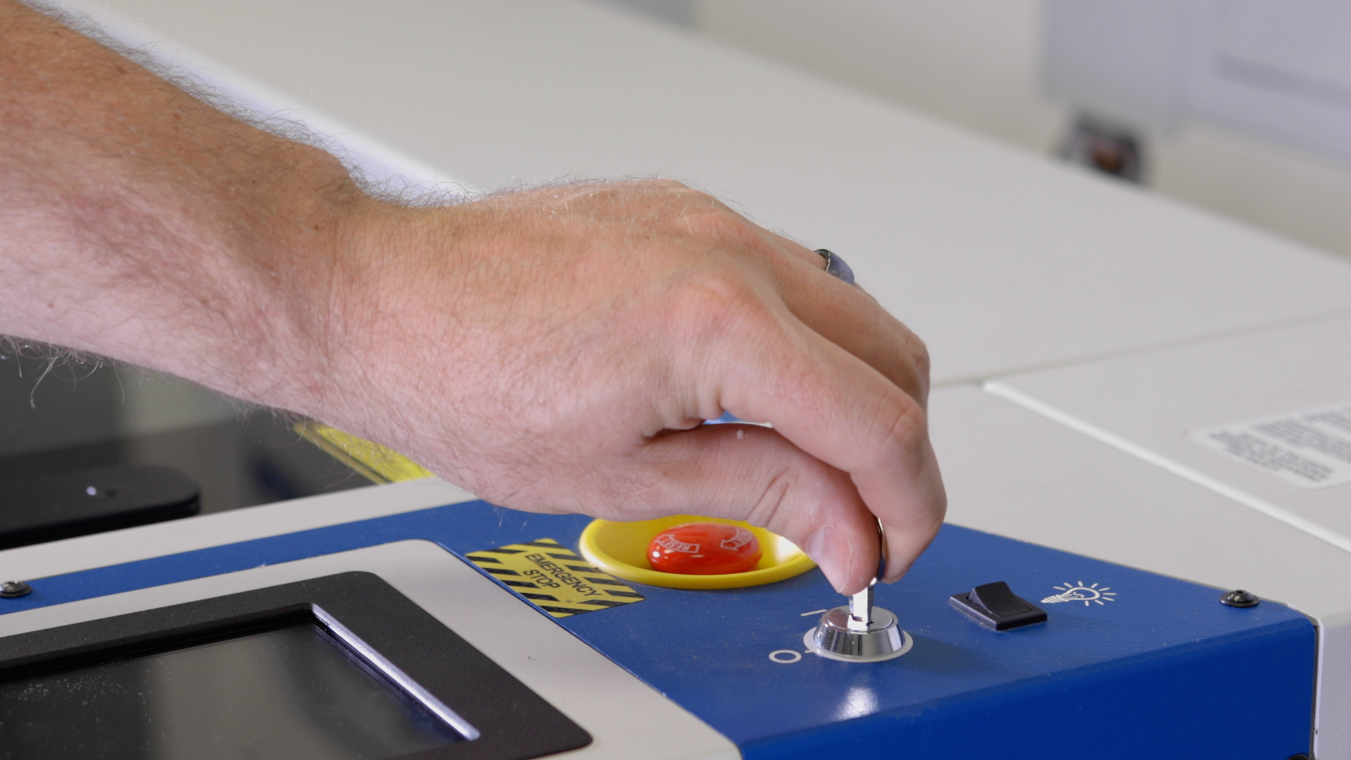
Plug in and power on the machine.
Open your preferred illustrating program and create a black raster box on an artboard that is:
- • For Pro 48: 46” or 1100mm wide
- • For Pro 32: 30” or 800mm wide
- • and Roughly 4” or 100mm tall
Set the speed to 100%. The power setting is unimportant, since we will be running the job with the machine lid open and the laser will not be firing.
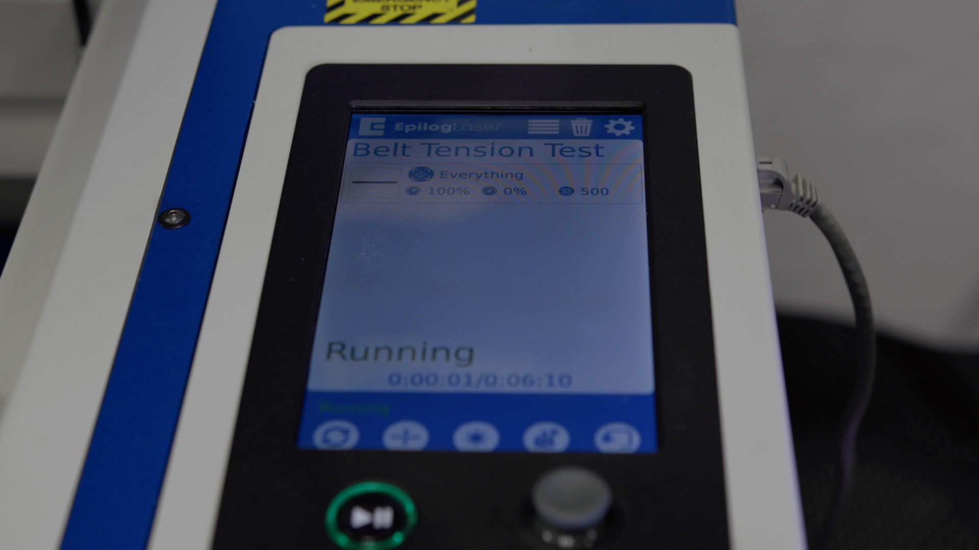
Send the job to the engraver and start the job.
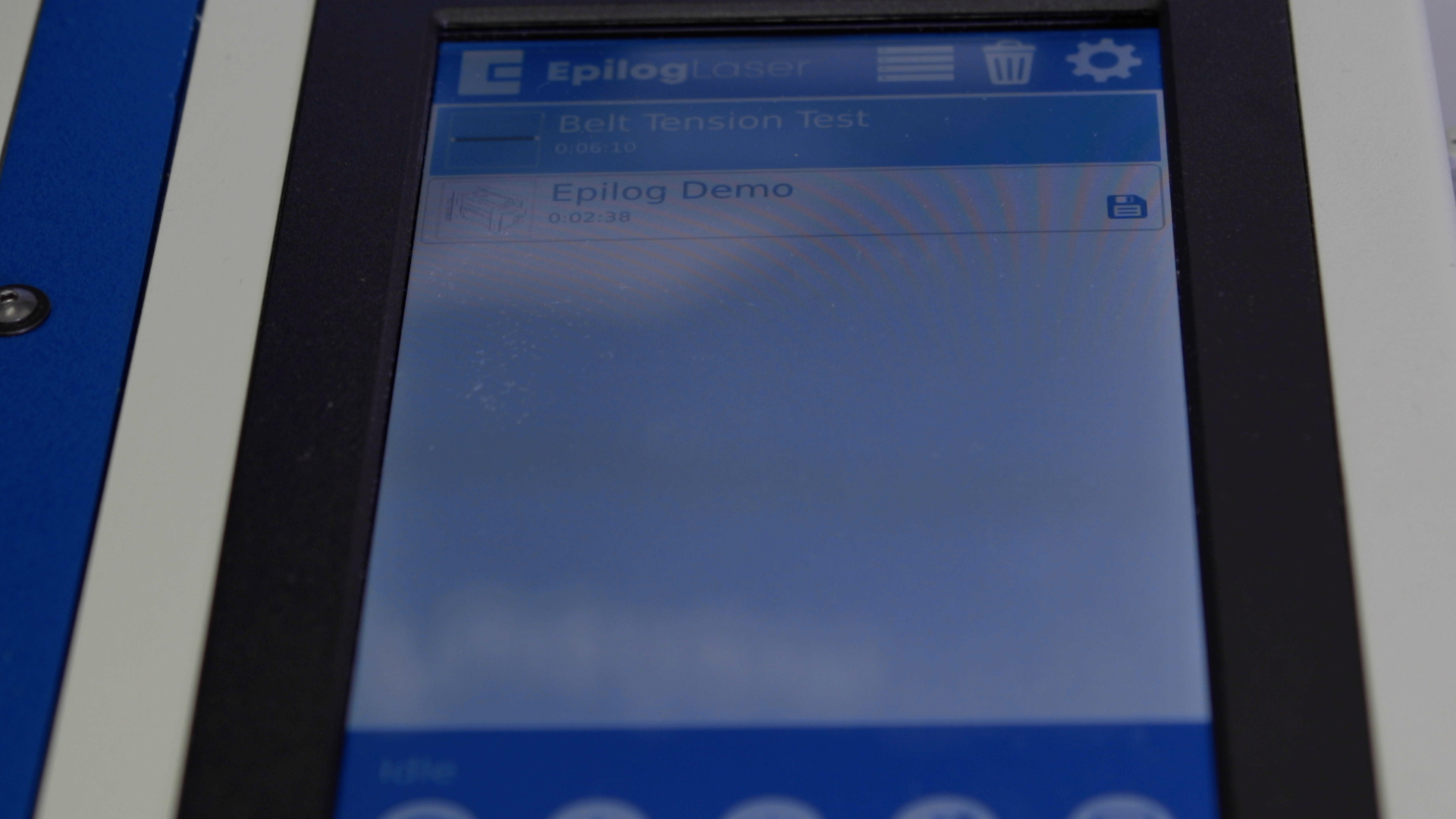
At the display panel, press the gear icon in the upper right-hand corner of the display to open the Settings menu.
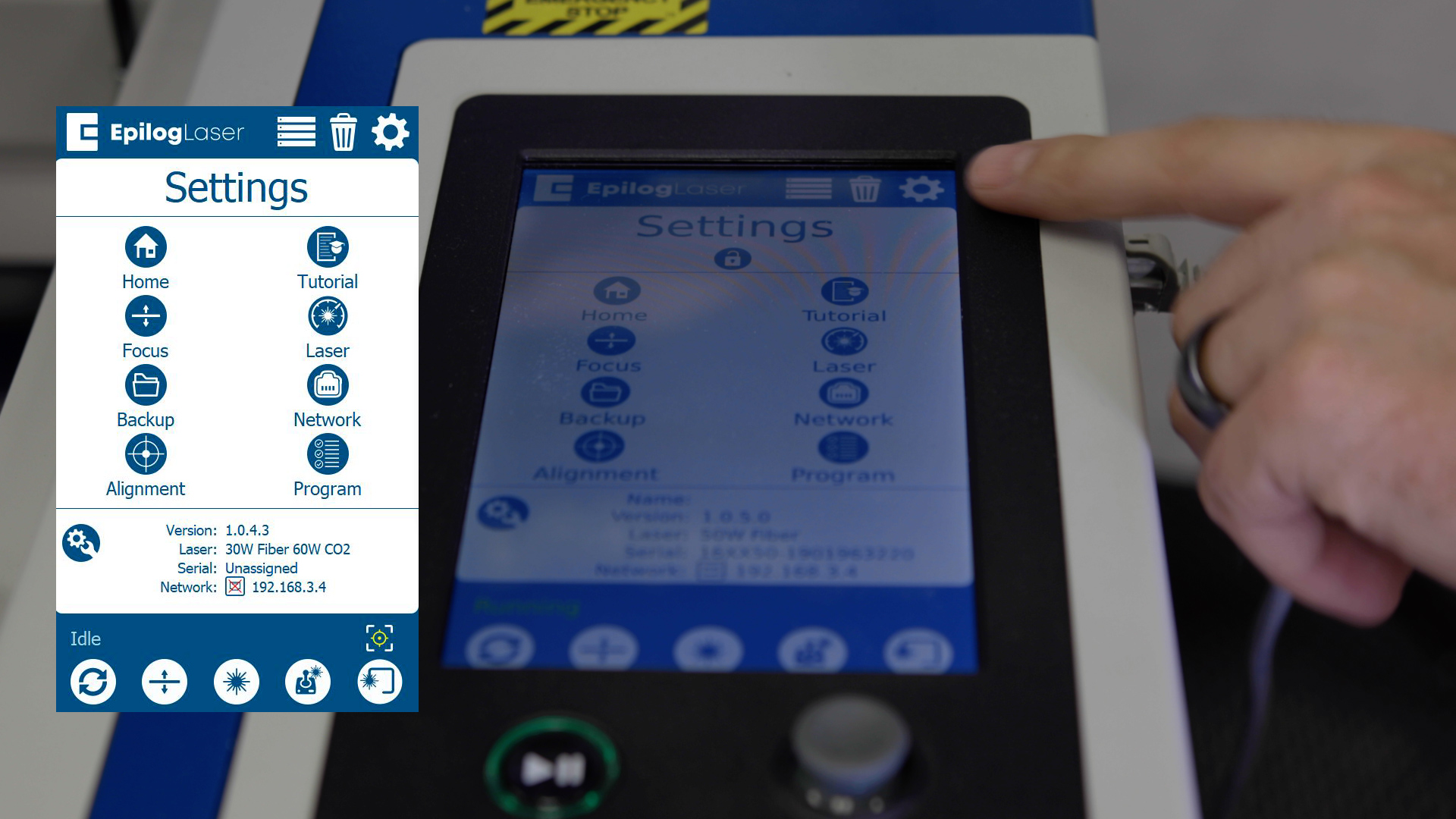
Press and hold the word “Settings” that appears at the touch of the touchpad to gain access to the Advanced Settings menu.
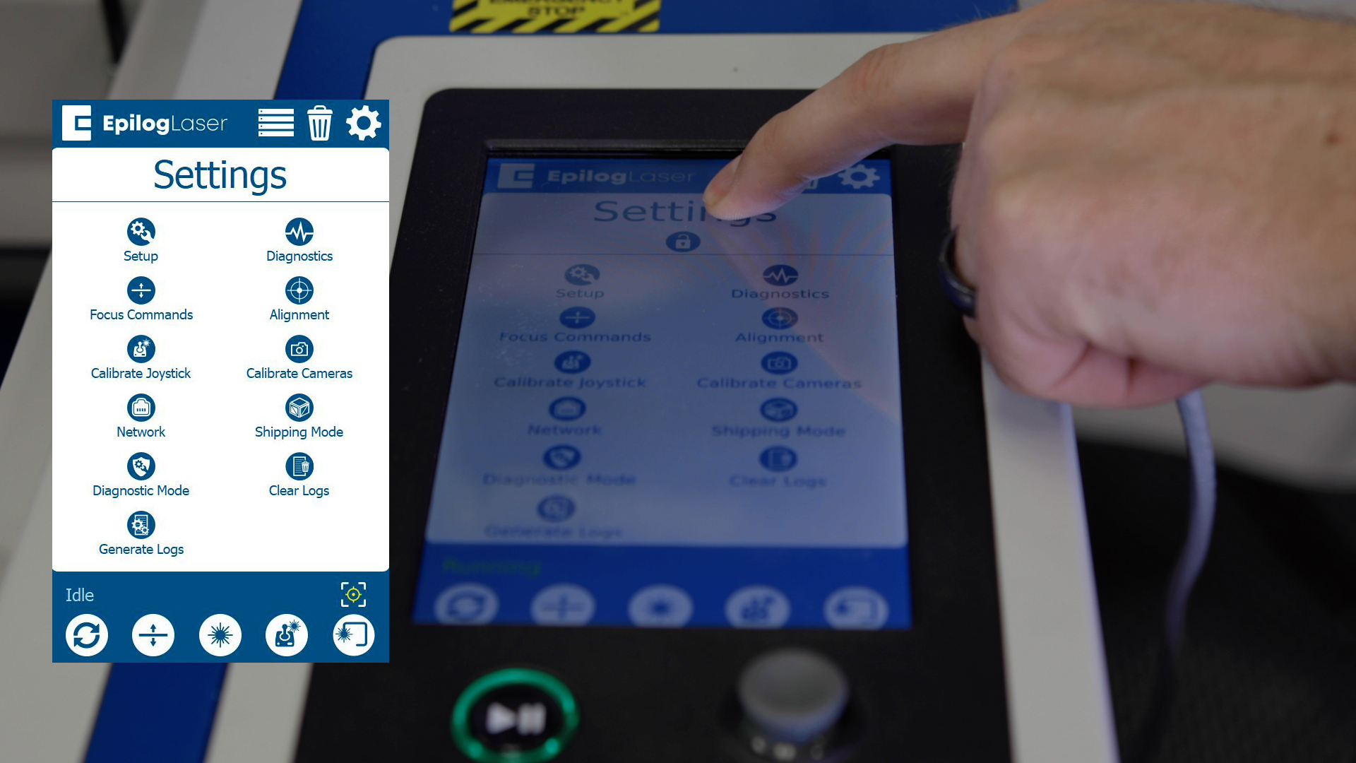
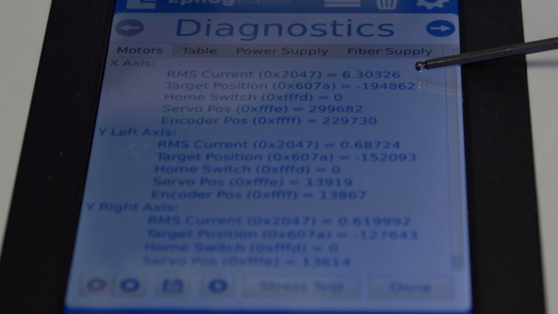
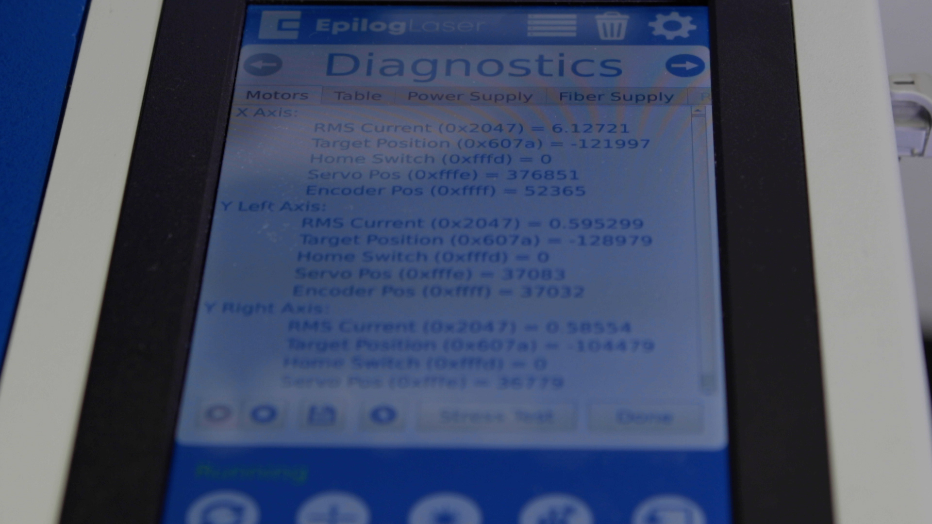
Once in the Advanced Settings menu, enter the Diagnostics menu and locate the RMS Current reading for the X-Axis Motor/Drive.
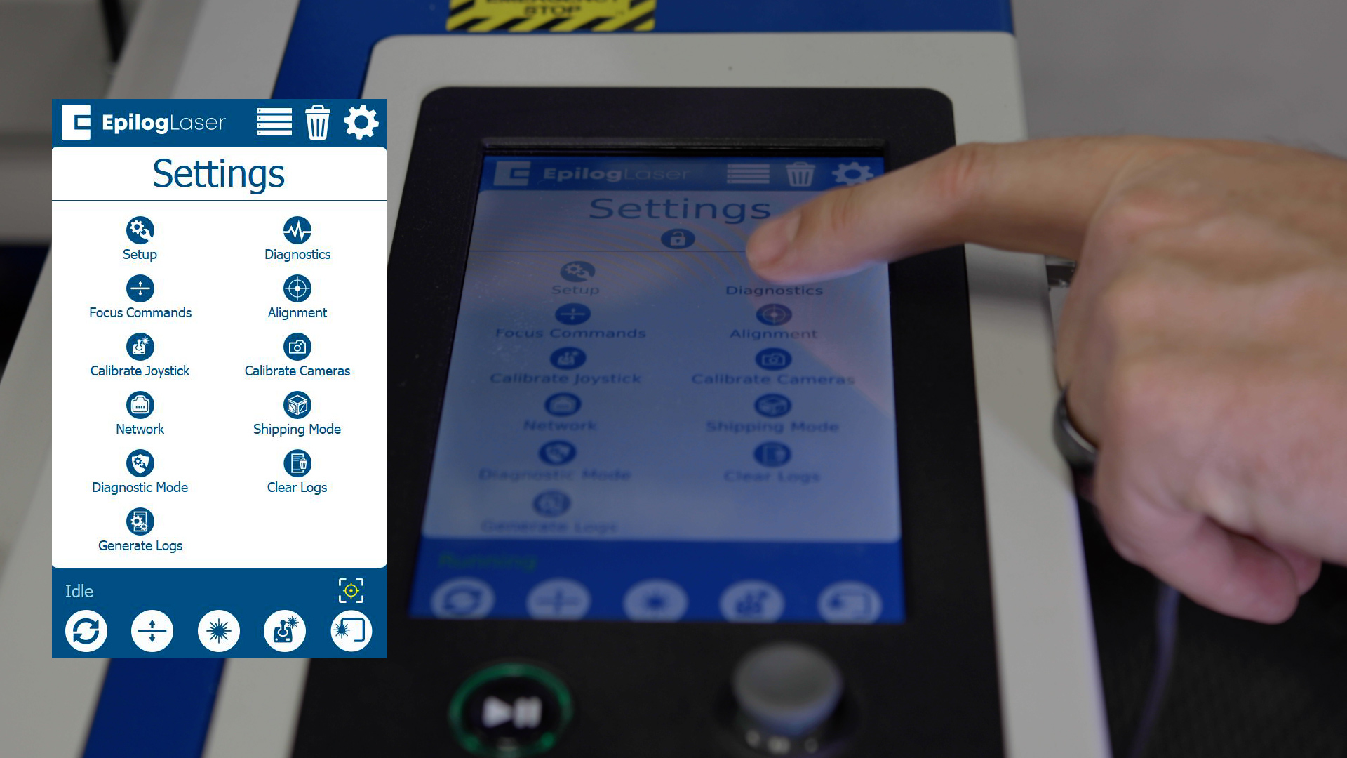
While the job is running, the x-axis motor RMS current should be between 5.2 – 6.2A.
If the RMS current is lower than this, pause the job and increase the tension on the x-axis belt by tightening the two (2) 7/64” tensioner screws on the x-axis idler assembly.
If the RMS current is higher than this, pause the job and decrease the tension on the x-axis belt by loosening the two (2) 7/64” tensioner screws on the x-axis idler assembly.
Once the optimal RMS current value has been achieved, tighten the four 7/64” idler mounting screws at the front of the x-axis assembly and the four 7/64” idler mounting screws at the rear of the x-axis assembly.
Replace the left side panel of the engraver.
You have now completed replacing the X-axis belt on the Fusion Pro.